I’ve been naughty and tried something that was out of my league…
I needed to shorten the GPIO pins on the Pisound because they are way too long to fit my project’s enclosure, but as I am clearly not a professional, I damaged 2 SMD components.
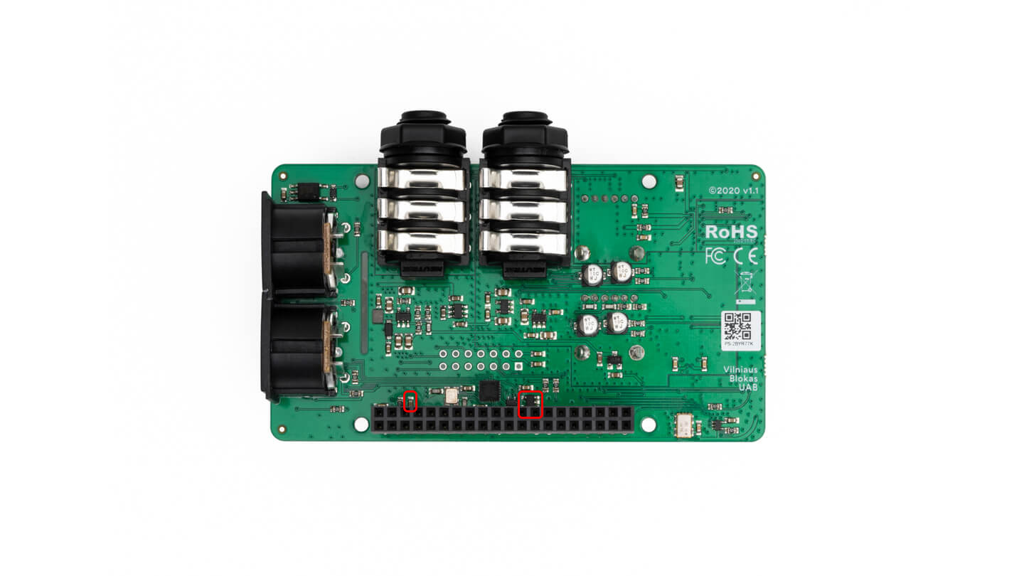
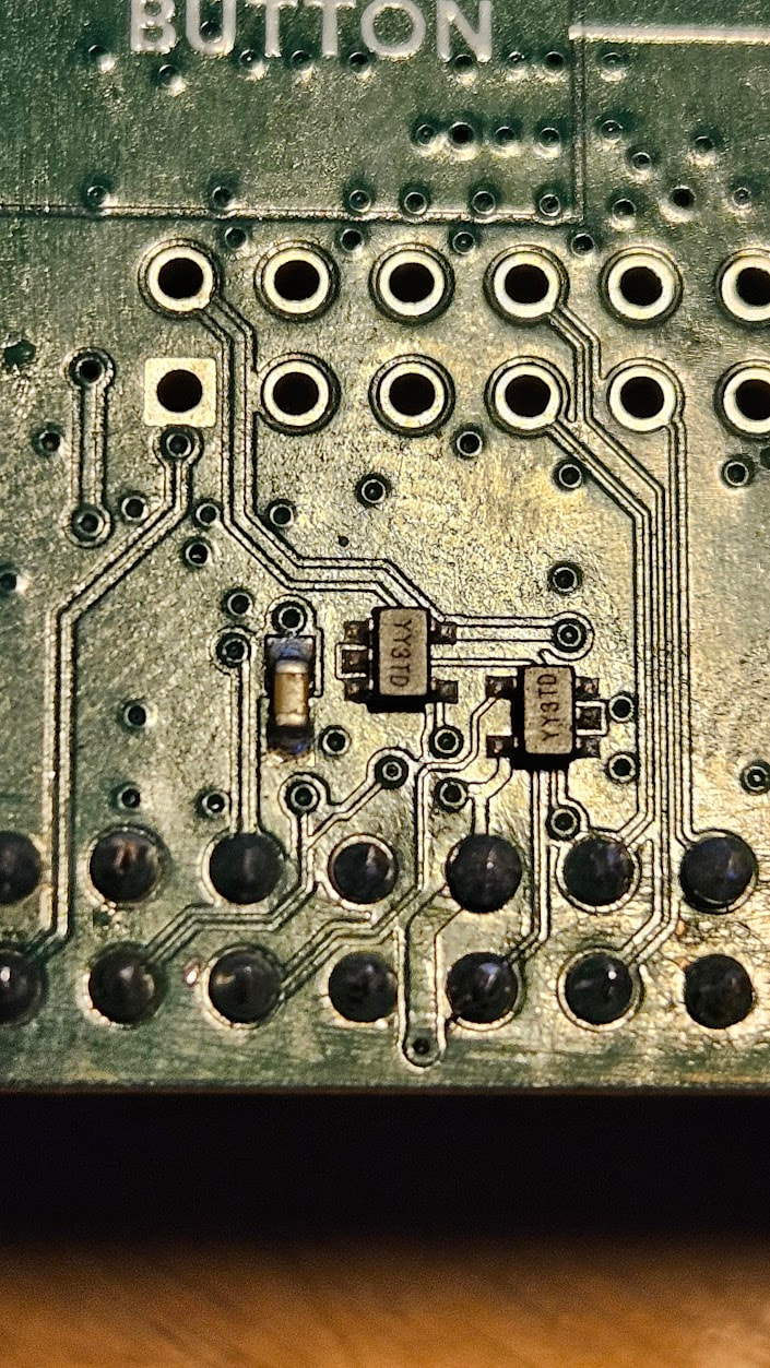
I broke a small brown two-pin SMD component (probably a capacitor?) and damaged another small 5-pin component marked M68Y (see the attached picture of their locations).
Before buying a new Pisound and throwing this one away, I want to try replacing the components to see if that solves the problem, even though it is hopeless.
There might even be more damage, as the process of unsoldering the GPIO was extremely painful as the pins wouldn’t come out. It was silly of me to work on such a precise PCB without the proper equipment, but I’d prefer trying to replace some cheap components in case I can save it!
Is there any chance I can get the references for these two components? I’ll ask a friend with the proper equipment to try replacing them.
__
Otherwise, if I buy a new board, is there any chance I can ask for a shorter GPIO pin length? (I’m guessing not, as it is probably assembled mechanically, but…)
The capacitor is 0603 100nF cap for debounce filter of the button and the IC is the EEPROM which you can’t simply replace, however, the workaround would be to do:
sudo dtoverlay pisound
to load the Pisound driver on demand or add this to your /boot/firmware/config.txt:
If it is a debounce, can i do tests without the cap just to see if the board still works ? (maybe with a temporary bridge to close the circuit at the cap’s position, for the tests)
Should I also make any bridge(s) on some of the EEPROM’s empty pins on the board now, to close a circuit too?
You can ignore the debounce cap, it only is meant to improve the button’s signal, it will not otherwise impact the operation of the board.
It would be a good idea to remove the EEPROM IC completely, in case it shorted inside or something.
Btw, the recommended approach to desolder the header would be to not even attempt to salvage it, as it’s a very tricky thing to do to save it (you’d have to be able to heat up all of the 40 pins simultaneously to remove it which is very difficult and can generate a lot of heat anyway that could impact other components). So the recommended procedure - accept that the GPIO header will be ruined, and simply cut it off, then heat each pin individually and pull out each pin with pliers while the hole is hot enough. Then wick / suck the solder out to remove the remaining solder, so a brand new header can be installed.
The headers of Pisounds are presoldered by the manufacturer.
So i can just run tests with both components removed from the board completely then apparently. Seemed counter intuitive to me, i thought i would need to close the circuit as the components are not there to do that purpose anymore.
I will test tonight and let you know.
Actually they were damaged while cutting the pins and/or trying to remove the cut pins (It was obivously impossible to desolder than much pins at the same time with a heat gun without having all the SMD things flying off the board , so I adopted the suggested strategy of cutting, but I just lack the precision and delicacy for that kind of work…)
Lots of capacitors serve a ‘bypass’ function where it connects to GND on one end and a signal it filters on the other. So it not being there simply loses some signal integrity. Lots of capacitors could be removed / scraped away, and the circuits would still work, but under some circumstances they could start misbehaving.
Best to cut the header close to the plastic housing of the header, as far away from the PCB. Easier to grip it out too.
1 - pisound seems to start allright, with the added dtoverlay in the config.txt I can see it in the patchbox-config > jack config.
I can use the button and I can see the input signal led for peak when sending sound through it.
Jack had a hard time startin after running its config again to select the pisound as sound card: it ended in this short error.
Jack service restarted! Waiting for Jack to boot… Error: Failed to start Jack service! Try different settings!
After trying different settings it now seems to be running as it shows enabled in green - but there are also a few errors when checking the status:
patch@patchbox:~ $ sudo systemctl status jack modep-mod-host modep-mod-ui
â— jack.service - JACK Server
Loaded: loaded (/lib/systemd/system/jack.service; enabled; preset: enabled)
Active: active (running) since Mon 2026-06-15 18:06:52 BST; 10min ago
Main PID: 3554 (jackd)
Tasks: 4 (limit: 2001)
CPU: 429ms
CGroup: /system.slice/jack.service
└─3554 /usr/bin/jackd -t 2000 -R -P 95 -d alsa -d hw:pisound -r 44>
Jun 15 18:16:48 patchbox jackdrc[3554]: JackRequest::ClientOpen write error nam>
Jun 15 18:16:53 patchbox jackdrc[3554]: JackPosixProcessSync::LockedTimedWait e>
Jun 15 18:16:53 patchbox jackdrc[3554]: Driver is not running
Jun 15 18:16:53 patchbox jackdrc[3554]: Cannot create new client
Jun 15 18:16:58 patchbox jackdrc[3554]: JackPosixProcessSync::LockedTimedWait e>
Jun 15 18:16:58 patchbox jackdrc[3554]: Driver is not running
Jun 15 18:16:58 patchbox jackdrc[3554]: Cannot create new client
Jun 15 18:17:03 patchbox jackdrc[3554]: JackPosixProcessSync::LockedTimedWait e>
Jun 15 18:17:03 patchbox jackdrc[3554]: Driver is not running
Jun 15 18:17:03 patchbox jackdrc[3554]: Cannot create new client
â— modep-mod-host.service - MOD-host
Loaded: loaded (/etc/systemd/system/modep-mod-host.service; enabled; prese>
Active: active (running) since Mon 2026-06-15 18:17:05 BST; 302ms ago
lines 1-23
BUT - I have no sound going out of the pisound (but maybe the settings on modep where left with no output last time I saved as i have a complex pedalboard).
AND - I can’t access the pedalboard or modep’s UI on the local network even though the status says all green and i tried to sudo systemctl restart modep-mod-host modep-mod-ui, and verified the IP hasn’t changed.
Would you have any idea of something else to check I might have forgotten to access modep’s ui and check if my audio routing has an output to test the pisound’s output ?
this line is truncated, but it might be using wrong sampling rate - Pisound supports only 48kHz, 96kHz or 192kHz sampling rates. Try using 48kHz instead.
[  228.658913] dma dma2chan2: dma2chan2 is non-idle!
[  232.708214] dma dma2chan2: dma2chan2 failed to stop
These indicate I²S transfer problems, meaning that there’s something wrong in the audio related traces or ICs. Those are on the top side, near the edge.
If you used hot air, some other parts may have moved or fell off, so inspect the board carefully if you see any unpopulated pads. (there’s 2 unclosed solder jumper sites on top side which are there by design)
Sadly I can’t seem to find the issue, no additional missing components for sure (appart from the 4 pads above the “volume” print you mentioned)
Can’t see any damage on a trace that would be obvious either.
What edge exactly are you meaning? Are they the 2 small 5pins ICs (YY3TD) close to the GPIOs on the top side ? They look ok…
I didn’t use hot air (the damaged where done when cutting the pins as short as possible) but the iron was close to many stuff while trying to remove the rest of the gpio pins, and i might have damaged the GPIO holes themselves I’m affraid, one of them looked like it might miss its copper (but hard to see now that a header is soldered back in)
I meant the ICs close to the pisound text. Ok, if you didn’t use hot air, then it might be the header. These pins in particular are involved, so double check if they are soldered well and you may also check with a multimeter if there are any shorts to neighboring pins or GND pins.
Just to close the case, I tried and checked and looked but I can’t get it to work whatever I do, so I guess I’ll just have to buy a new one… That’s just a big waste of money (and material) but I’ll keep this one for components somehow (for a future out-of-my-league-project ).