Hi,
I don’t understand well the signification of the colors in the pinout image. The round black (2, 4, 6, 9, 14, etc.) are said to be Power supply pins. But power supply of what? Does it mean, as I understand, that I cannot use them?
And so, if I need to put the pisound away from the raspberry pi (because it is connected to the raspberry touch screen 2), I have to wire all of them too?
Pin 6 on RPi is ground. I should be able to connect to, should I?
Thanks in advance,
Gaël
Sorry. Stupid question. After checking, most of them are just the GND pins… but anyway, are they all used by pisound?
I just tried to connect all pins except blue and green ones with Dupont wires but my pisound was not working. Its devices did not appear on qpwgraph. Just to be sure I not burned it, I connected it directly again and it worked…
So, should it just work with Dupont wires?
P.S.: I will check tomorrow all Dupont wires and then the connections with a multimeter to ensure it is not just a faulty connection.
You can look at https://pinout.xyz as the pin meaning reference. You should make sure to connect all of the pins marked with the red color. You must connect +5V and +3.3V pins as well, and as many GND pin as you can manage.
To keep it simple, you may just take a 40 pin male ↔ female ribbon jumper cable and connect all of the pins in the correct sequence together.
Double check your connections with a multimeter before powering on, to avoid damaging the electronics. What to check for - whether pin 1 on Raspberry Pi connects to pin 1 on Pisound, same for pin 2, up to pin 40. Additionally, check if +5V net is not connected to +3.3V, as well as if both of them are not connected to GND.
Thanks a lot for your indications. I have doubts concerning the pinout described in the documentation.
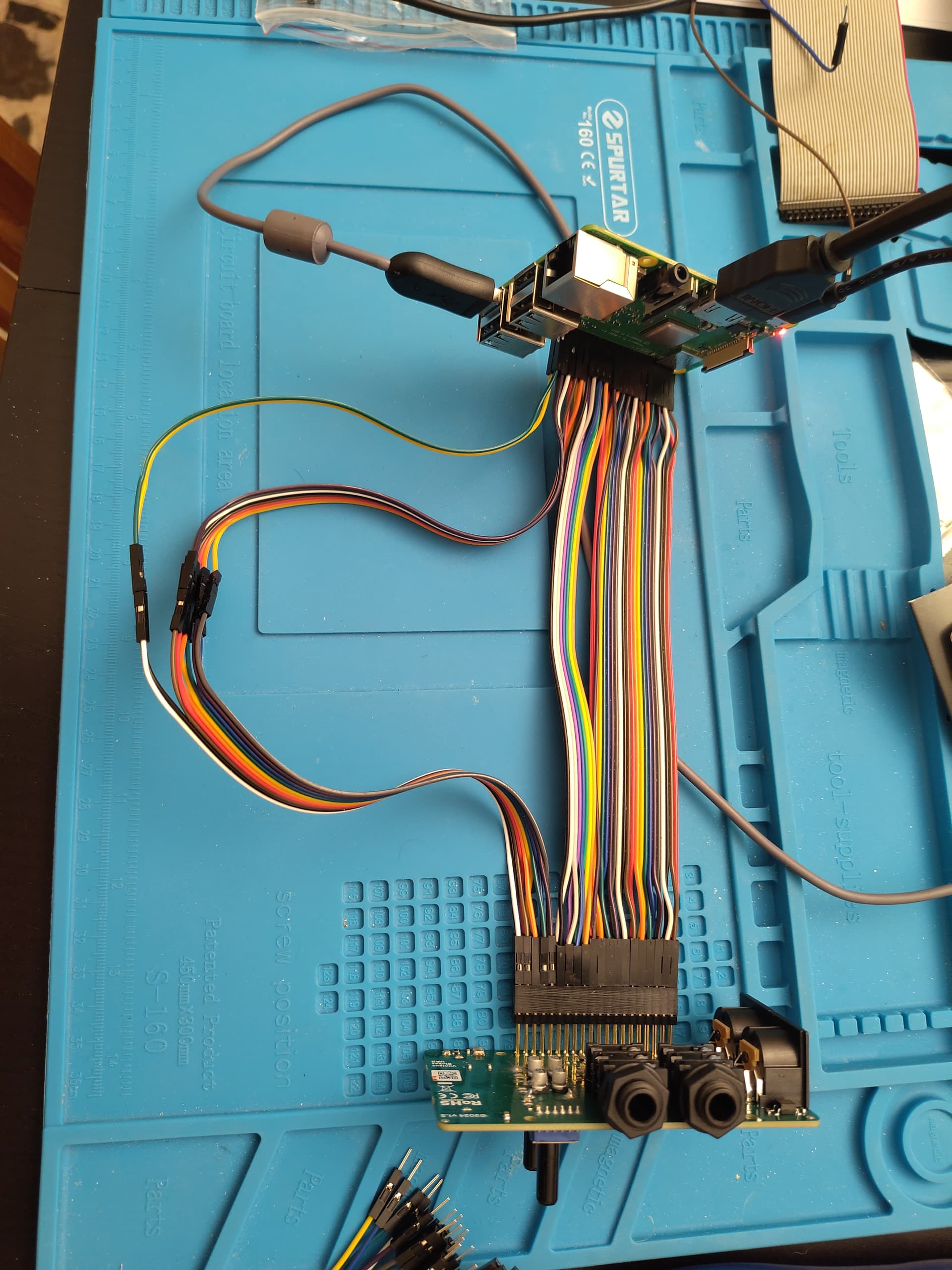
I have reproduced it using Dupont cables and it did not work:
It is not evident on the photo, but I have checked all connections 2 times with a multimeter, from the back of of each card.
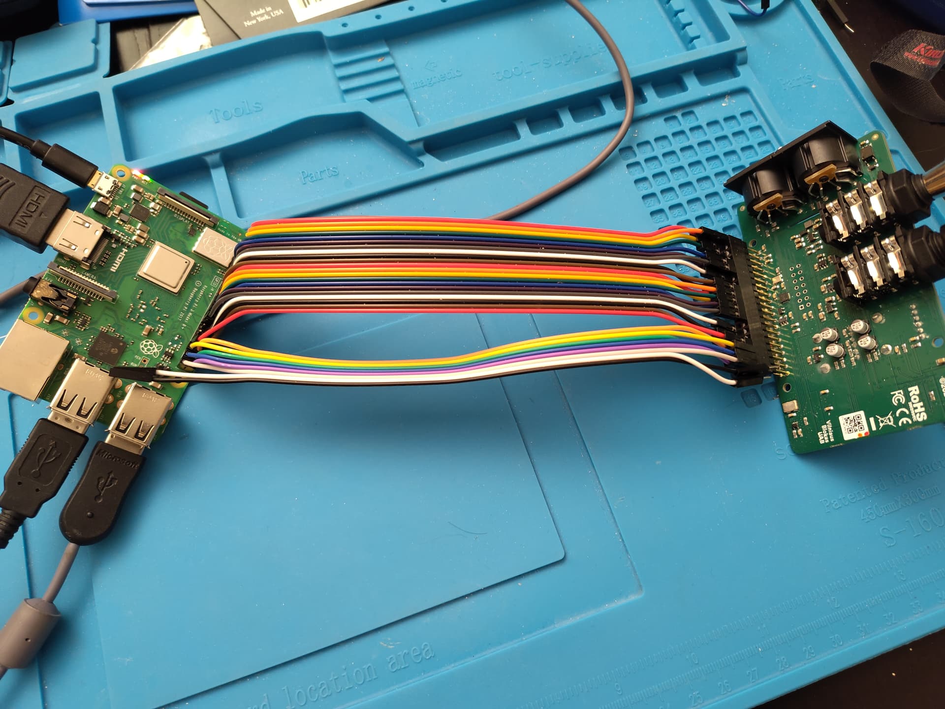
When connecting all pins, it works:
Any explanation?
I will try to remove the wires supposed to not be necessary for pisound one by one and see when (and if) it stops to work.
I know that I will probably end using a ribbon cable and solder wires to the repeated connections (It will be way more resistant) but I want to understand precisely what happens.
I finally understood what happened by removing supposedly unused wires one by one. I successfully removed all those that are green on the documentation. It stopped working when I removed the first blue!
Well, I’m probably silly but the documentation says something like “reserved for hats”. But not “and thus used by pisound”… And so I initially supposed that I should not use them but that pisound was not using them neither. Yes, it is hat itself, but as it was stated differently I supposed they were for other possible hats.
So I suggest updating the documentation for dumb people like me.
The EEPROM I²C pins are for discovering the features of the attached hat so the system knows which drivers to load.
It is possible to leave them disconnected, in that case you should add this line to your config.txt:
dtoverlay=pisound
OK. Thanks. I would suggest to make it explicit on the documentation.