Hello from Seattle, we’re trying to power an electret microphone (hydrophone, actually) with the Pisound HAT and wonder:
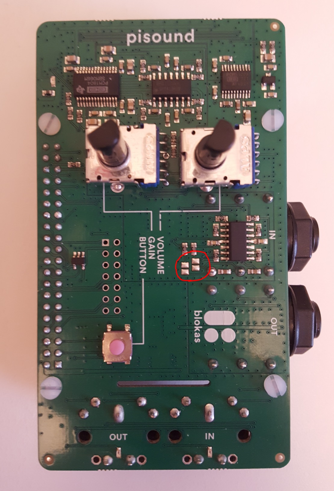
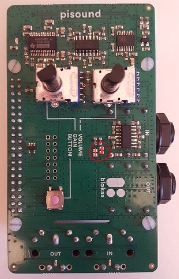
Where exactly are the “two solder jumpers near the input port”? Would it be possible to add a diagram or annotated photo to the guidance we’ve read (and puzzled over) here – https://blokas.io/pisound/docs/audio/#5v-bias-solder-jumpers , or provide one to the community forum??
Thanks @Giedrius . To be completely clear, we’re talking about jumpers that make a connection that is parallel to the word “VOLUME” (as opposed to diagonally), right?
Can you confirm I should solder jumpers where the red lines are in this new version of your image?
I’d like to write my experience when we soldered these jumpers.
After we soldered the jumpers a new weird noise was introduced even when microphone wasn’t plugged in.
Tried changing from RPi’s original AC adapter to power-bank and it’s the same.
When I connected electret microphone I’ve got a lot of noise, and I would really give some gain to hear it loud, but then noise would became a lot louder.
Did anyone used PiSound with electret microphones, and have you guys noticed the same?
Which microphones you used?
For my purpose, none of noise reduction filters shouldn’t be used so software solution isn’t a way to go, sadly…
Any thoughts how “fix” this?
Mics I’ve tried:
RODE VideoMicro
Sony ECM battery powered condenser
BM700 from China, cheap mic, has least noise, but still noticeable
some lapel microphone, no name
dynamic karaoke microphone
All of these mics sound great when plugged in for example Zoom H4n, no noise…
Oh and, I’ve noticed now that somehow (I think) electricity that should go to microphone some of it goes to the headphones, with low impedance headphones it’s more noticeable, with high impedance ones there’s less noise but still noticeable!
Sorry, @vedranius, we’re using an underwater microphone (hydrophone), so I can’t offer any experience with electret microphones. Maybe @Geidrius has some thoughts about your results?
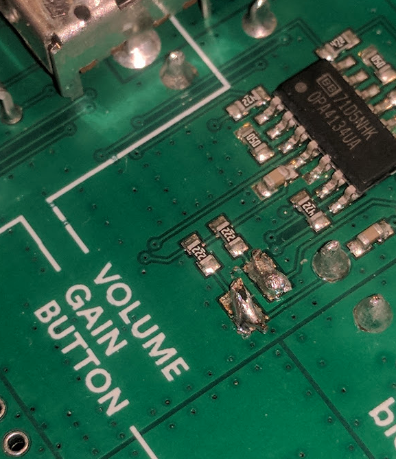
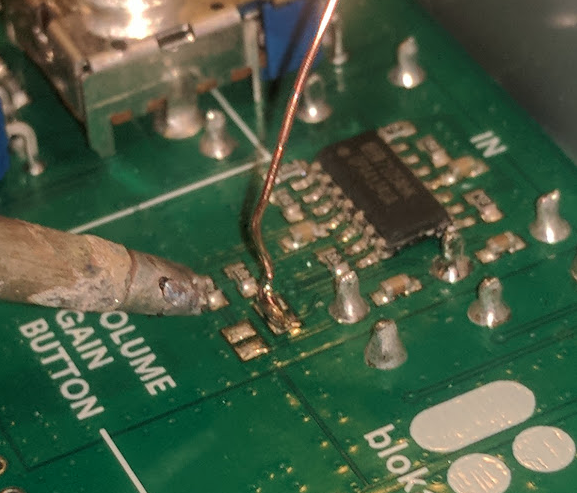
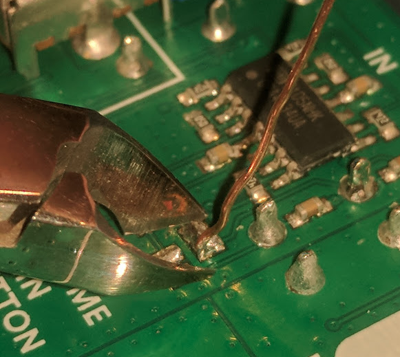
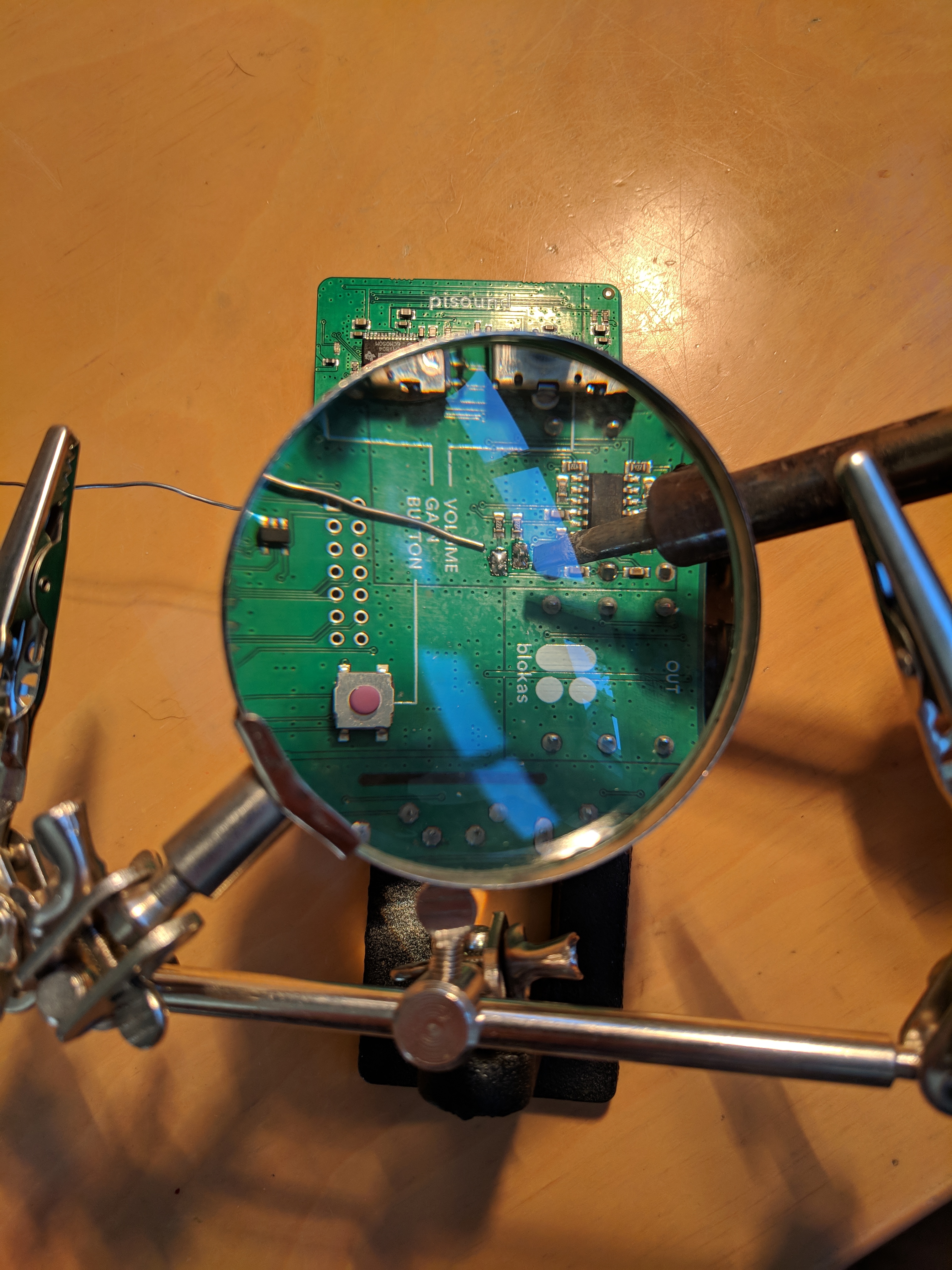
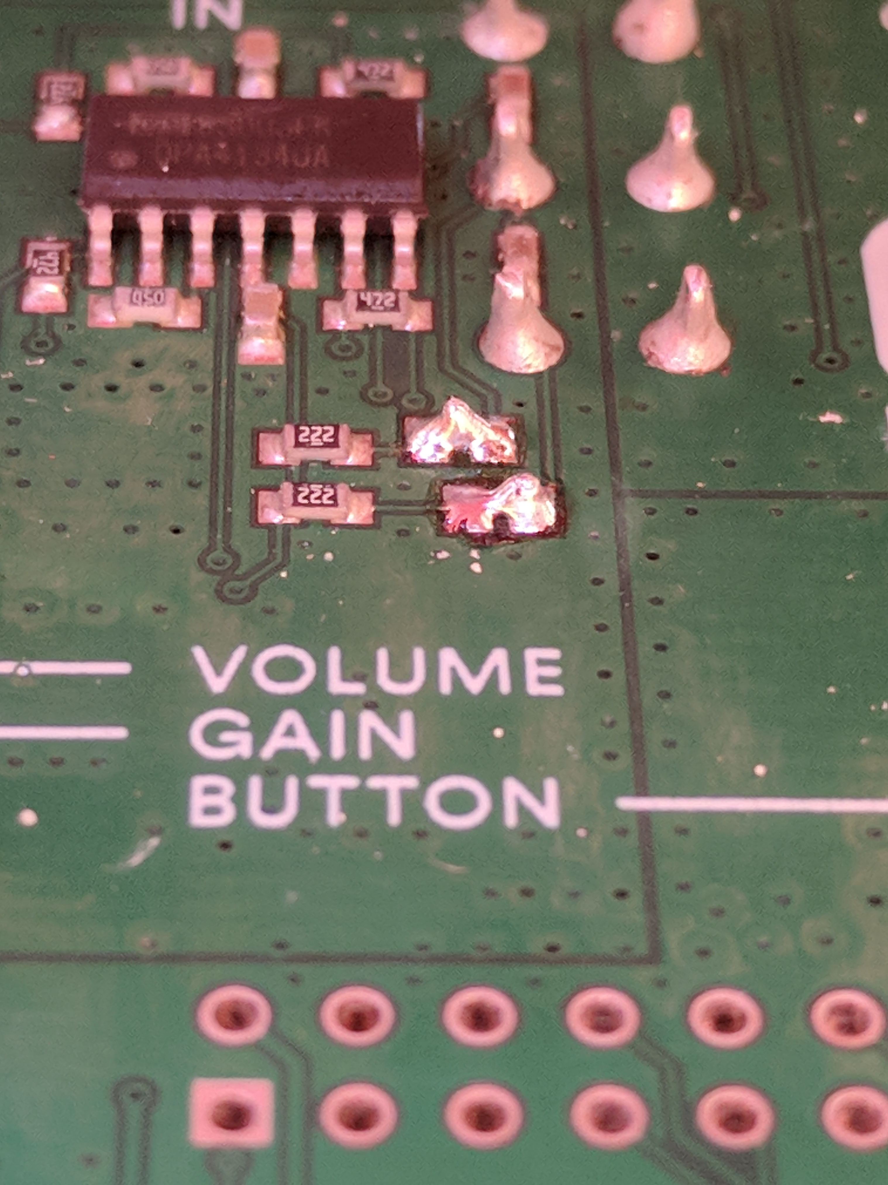
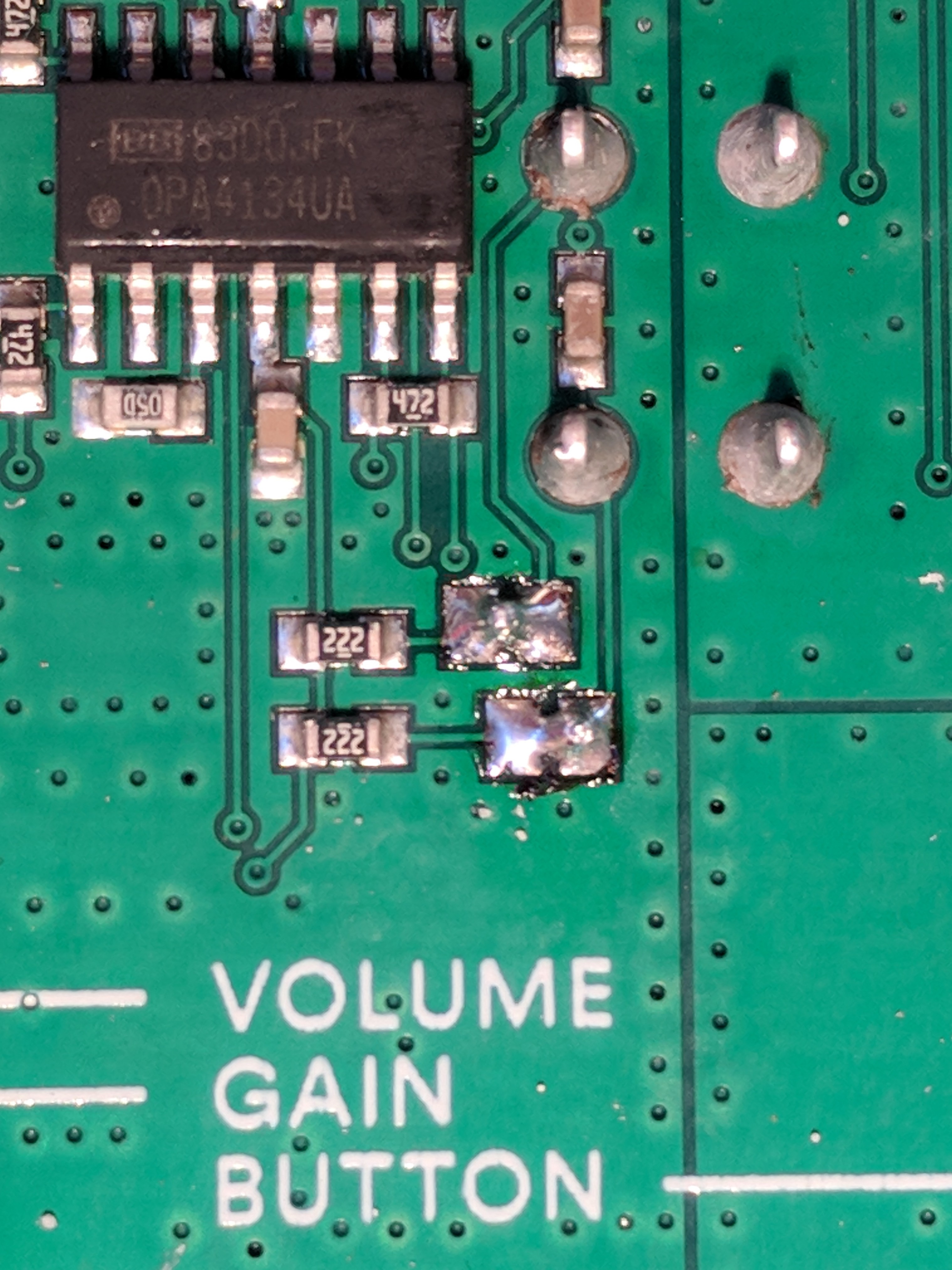
This time we tried a solder bridge instead of the wires. It was pretty easy, though it seemed important to minimize the time during which the soldering iron tip was in contact with the board. Here are the results:
Also, I liked this explanation you provided back in 2017 – “The one that is closer to VOLUME is for the left channel, the other is for the right channel.” – but might adjust it slightly (having now studied the traces on the board) to something like this:
The jumper that is closer to the “VOLUME” text is for the left channel (tip of the 1/4" jack", while the other is for the right channel (ring of the 1/4" jack).
Having now destroyed quite a few Pisound boards by soldering these jumpers when my iron was a little too hot, I’d like to make two suggestions:
Offer a version of the Pisound where the jumpers are pre-soldered professionally and then tested to ensure both ring and tip are providing the intended 6V bias power
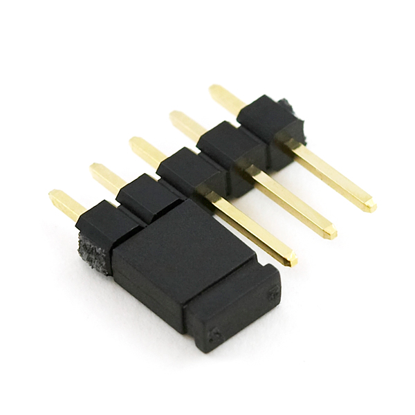
Redesign the board to use a 2-pin header (e.g. this one from SparkFun) so all the user needs to do is add a cap.
Thank you for the reminder. Could we use the 3rd photo you posted in #15 for documenting this?
Yeah, it’s easiest to build the bridge with a rather cold soldering temperature, like ~315C. If the soldering iron used does not provide temperature control, it can be worked around by heating the iron up and disconnecting the power supply, waiting a little bit for the iron to cool off. Remember that the solder likes to stick to hot surfaces, so both solder jumper pads must be heated at the same time, and a somewhat excessive amount of solder has to be provided, ideally directly at the pads, so that a bridge forms. The soldering iron should be moved away in a rather quick motion.
Having a factory assembled variation such as this would add to the costs of the product, but for limited size batches I think we could handle it manually as a custom order, you may contact us directly to arrange that.
Yes, please use any photos that are helpful, @Giedrius . And thank you for the technique guidance regarding the optimal jumpering process.
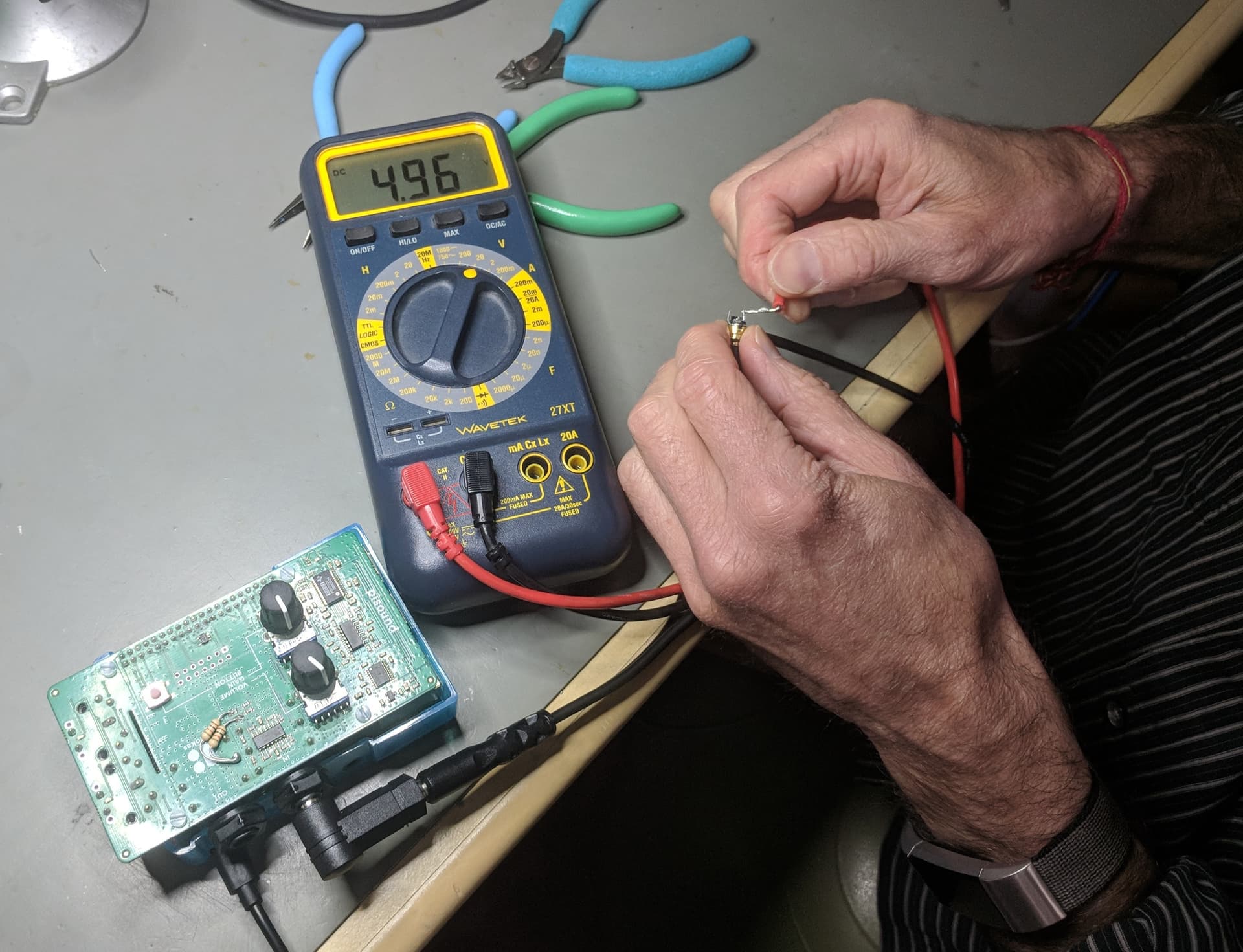
By the way, this is the method that Joe Olson of Cetacean Research Technologies used to reduce the bias power voltage from 6.0 to ~<5 volts for his SQ26-08 pre-amplified hydrophone: