Bias power at 6.0V instead of 5.0V after soldering jumpers?

Hello,

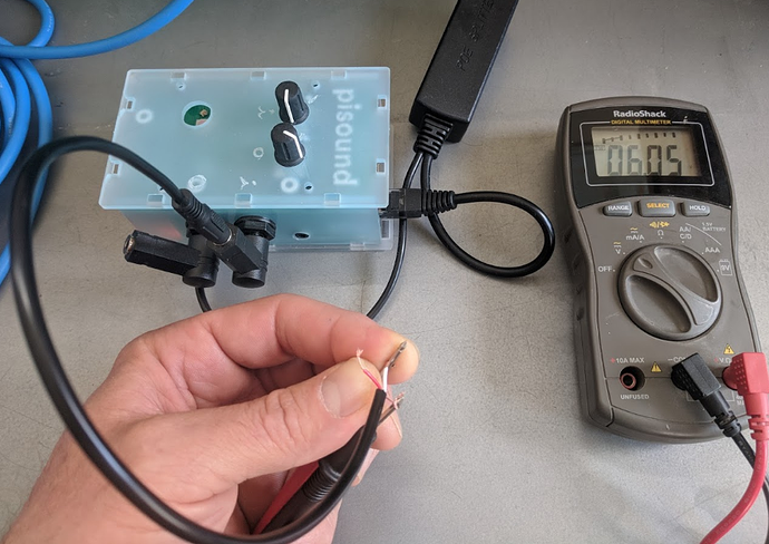
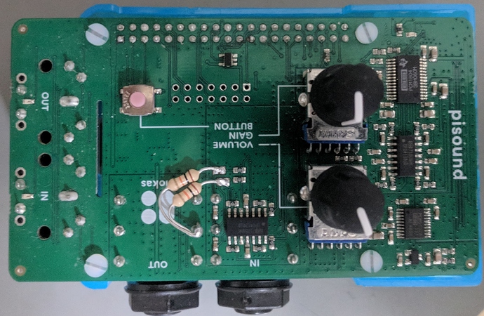
I was preparing to test a hydrophone that wants a “hot mic” voltage of 2.5-5.5V and decided to test the voltage provided by the Pisound after soldering the 5V bias jumpers. I was surprised to find the voltage between the ground/shield and either red/tip or white/ring to be 6.05 volts, rather then the 5.0 that I expected.

Here’s the voltage between red and ground wires:


(In this photo it looks like the black multimeter lead is also touching the white wire, but it’s not.)

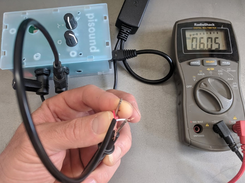
Here’s the voltage between white and ground wires:

The same measurement on a 2nd Rpi3B+PiSound device in which I’ve soldered the 5V bias jumpers yields 6.02V. There’s a third I could get tested, but it’s currently in California…

Is this a feature or a bug? Any thoughts, @Giedrius?

Best regards,
Scott in Seattle

Hi, the bias voltage is meant mostly for electret condenser microphones which accept a wide range of voltages, however, I will update the documentation to clarify this. (It’s 6V / 2.2kOhm current source)

To get 5V bias voltage, a 10kOhm resistor can be soldered between the signal and ground wires, this can be done at the end of the microphone.

However, we’d still like to double-check with the datasheet of the microphone you’re using - what is the model of the microphone you’re using?

1 Like

Thanks, @Giedrius. It’s an underwater microphone (aka “hydrophone”) provided by my colleague here in Seattle, Joe Olson.

It is called the SQ26-08 – https://www.cetaceanresearch.com/hydrophones/sq26-08-hydrophone/index.html – and I think it is using this pre-amplifier – https://sensortechcanada.com/preamplifiers-and-electronics/hydrophone-preamplifiers/phantom-powered-preamp/

Perhaps in future Pisound models it would be better to provide 5V? I don’t know if there’s any standard for electret microphones, but I’m getting hints that while 3-9 volts is acceptable, many devices may provide 5V… e.g. http://www.epanorama.net/circuits/microphone_powering.html (especially Note 2)

I’m curious – was there a reason your documentation says 5V when actually 6V is provided via the bias power jumpers?

My current plan it to try powering the hydrophone in two ways and compare the sound quality. First, we’ll try reducing the 6V from the Pisound input jack to 5V with a resistor as you suggest. Second, we’ll try providing the hydrophone signal to the Pisound via the input jack, but power the hydrophone from either one of the Rpi’s USB jacks or the power-over-ethernet (which I’ve already installed to power the Rpi).

Any opinions about this plan, or suggested alternatives would be welcome!

Hi, I’m an aged engineer.

The electret microphone is an active device, inside there is the microphonic capsule and a FET (field effect transistor).

The correct use consists to connect a load resistor in the range 2 to 10 kOhm to a positive supply V+. The voltage of the supply contribute to settle the working point, a point in the V, I diagram.

The gain is moderately proportional to the V+ supply voltage, and is directly proportional to the load resistor.
The breakdown voltage of the FET is in the range of 10…30 V or more.

A little sophistication is obtained substituting the resistor with a “constant current” diode of about 2 to 5 mA.
See, for example this page:

https://www.mouser.it/Semiconductors/Discrete-Semiconductors/Diodes-Rectifiers/Current-Regulator-Diodes/_/N-ax1ml

This diode is a device that maintains across the circuit the nominal value of current, not depending (with a good approximation) by the supply voltage, if the value is greater than a threshold level.

The advantage of this solution is the greater gain obtained.

Regarding a precedent question about the capability to do a real-time acquisition, I suggest to use (with raspbian 9) the alsa library, that is named alsaaudio in Python.

The python code, e.g. get_audio.py, can be compiled to binary using the python package nuitka:
nuitka --python-version=3.5 --recurse-none get_audio.py

obtaining the output get_audio_exe.

Then get_audio_exe can be executed also with very strong priorities:
sudo ionice -c 1 -n 0 nice --20 chrt -r 99 get_audio_exe

The command uses the highest real-time priority: chrt -r 99, the highest I/O priority: ionice -c 1 -n 0, and the most performing “niceness” for the application: nice --20.

The following procedure illustrate how to obtain the capability to run real-time audio processes:

  1. Before modification:
    to see the pi user priority enter ulimit -l -r

    ulimit -l -r
    max locked memory       (kbytes, -l) 64
    real-time priority              (-r) 0
    

    for the root user

    su root
    ulimit -l -r
    max locked memory       (kbytes, -l) 64
    real-time priority              (-r) 0
    

    the root user is not in the audio group, add it to that group:

    adduser root audio
    
  2. modify /etc/security/limits.conf to allow negative “nice” values:

# ADDED --------------------------------------\
pi             -      nice           -20
root           -      rtprio           95
root           -      memlock    unlimited
# ADDED --------------------------------------/
  1. modify: /etc/security/limits.d/audio.conf

remove comment from last line: @audio - nice -19
as follows:

# Provided by the jackd package.
#
# Changes to this file will be preserved.
#
# If you want to enable/disable realtime permissions, run
#
#    dpkg-reconfigure -p high jackd

@audio   -  rtprio           95
@audio   -  memlock    unlimited
@audio   -  nice           -19
  1. reboot

  2. Check priorities:
    user pi:

    pi@raspberrypi:~ $ ulimit -l -r
    max locked memory       (kbytes, -l) unlimited
    real-time priority              (-r) 95
    

    user root:

    su root
    root@raspberrypi:/home/pi# ulimit -l -r
    max locked memory       (kbytes, -l) unlimited
    real-time priority              (-r) 95
    
  3. Pay attention the command: ionice -c 1 -n 0
    as well for: chrt -r 99
    are accepted only when operating as root.

nuitka --python-version=3.5 --recurse-none get_audio.py

The resulting complete command is:
sudo ionice -c 1 -n 0 nice --20 chrt -r 99 get_audio_exe

I arrived to the illustrated procedure, because the Raspberry Pi 3B with raspbian 9 gived very frequent buffer overrun, running the get_audio.py acquisition code, also using a console without the boot into the graphic environment.
Now the code run flawlessy in graphic mode and is insensible to the load of other running code.

(I hope the Devil don’t dropped some mistake reporting the commands to allow real-time. For the lexical consistency I checked and corrected my text translating it with Google to my native language, the italian).

Bye.

Lorenzo
2 Likes

Thank you Lorenzo for your input, it’s very detailed! I have edited your post to add some formatting to configuration / command parts of your post.

It’s an oversight from our side, sorry about that, the documentation should say 6V / 2.2kOhm. Thank you for noticing this. It is still usable for most electret microphones, but since your microphone strictly specifies power supply between 2V and 5V, some additional tweaks seems are required using the resistor, or powering off of the 5V pins on RPi / Pisound.

The 6V bias comes directly from the analog 6V supply that’s used for the Pisound’s op-amps, it is provided via some power supply circuitry, including filtering, and it should be more clean and stable than what the 5V pins on RPi / Pisound provide. You should try both ways and see which one is easier and works better for you.

The easiest way to access 5V pin is via the unpopulated header on Pisound: Detailed Specs - Pisound Documentation. (pin number 2)

1 Like

Hey @Giedrius, I think I confused you. Sorry!

I was curious about why you made the design decision to provide 6V instead of, say, 5V. (I’m not really concerned about the discrepancy in the documentation, though I’m glad you’re now aware of it.)

I’m curious because my impression is that majority of recent/modern devices provide 5V (or less) for microphones via their bias-power or plug-in-power (PIP) jacks. Is there a standard, or is one evolving over time? For examples, see: this (2012?) web page on powering microphones which suggests there’s a more common 1.5-5V range within a overall range of 1-9V; this 2015 electronics.stackexchange answer about 2.5V/3.2V/4.2V being common from user Fizz; this 2016 Audio-Technica post that hints at an upper limit of 5V for their microphones; or this 2017 mention of 5V by Shure.

I’m not aware of any such standard or evolving commonality in underwater microphones (“hydrophones”), though I’m still pretty early in my mapping of hydrophones in this public Google spreadsheet where I’m trying to note which hydrophones have pre-amplifiers and the nature of their power requirements. It seems many hydrophone systems want 12V, possibly because that is commonly available on many boats…

If you don’t (still?) have a strong argument for providing 6V in the current Pisound, might you all entertain the idea of providing 5V instead on the jumpered input jack of future versions of the Pisound?

All the best from Seattle,
Scott

Hey @Giedrius,

My colleague Joe and I decided to try utilizing the Pisounds bias power first – under the theory that it is likely cleaner than what we could get from the Raspberry Pi (pins or USB ports). We may try both/other ways eventually, but wanted to see what you thought of this approach:

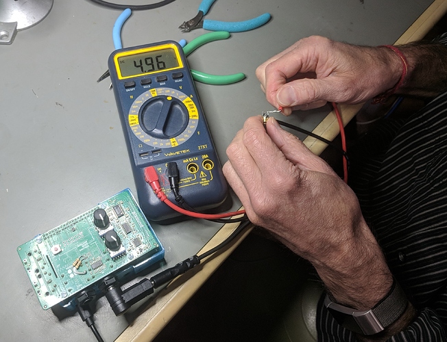
  1. Joe soldered 10kOhm resistors between the jumper positions and the middle/left pin of the input jack, like so:

  1. We plugged in the Raspberry Pi (via POE) and tested the voltage (via a 90-degree stereo 1/4"-1/8" jack and this stereo-mono splitter) and got 4.95V on the mono input jack (where Joe’s hydrophone wants it). Here’s one view of the result:

I’ll be testing this new hydrophone set up over the next week and will share how it goes. In the interim, do you have any opinion about whether we should replicate this approach for future hydrophone systems, or do the electronics in some other, better way?

Thanks for all your support and interest,
Scott in Seattle (WA, USA)

1 Like

There is no standard for electret microphones that would say 5V must be used - they need a current source with 3V~9V voltage, Pisound provides one by basing it off of the 6V analog supply which is used already used for other parts. Getting it down to 5V from 6V wouldn’t be effective, as additional parts would be required and no real benefit gained.

Keep in mind that a current source is not the same thing as a power supply.

By the way, I have discussed with our electronics engineer, we think that it’s best for you to connect the Raspberry Pi’s 5V power supply pins to your microphone, as it specifies 2 - 5Vdc as the power requirement, so that probably means no additional resistors should be used in the power net.