Hi all!
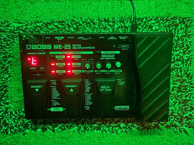
Recently I completed the first phase of building a custom MIDI foot controller for use with MODEP. It has definitely made playing and practicing a lot easier! Here’s a picture of it:
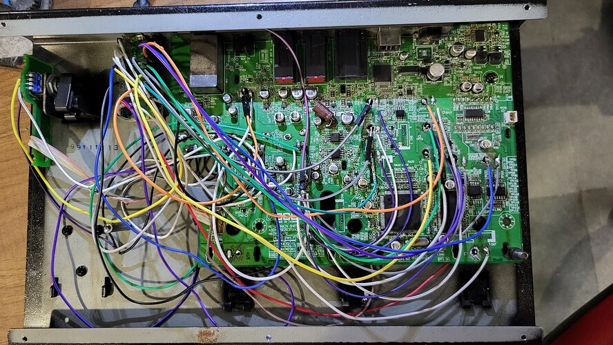
Yes, I kinda took the easy way in regards to the hardware and got an existing hardware unit. I figured this would save me from all the hassle of finding all the switches and knobs and getting an enclosure built for them. I found this Boss ME-25 advertised as “not working”, which was perfect, and got it for real cheap. I decided to use the Pi Pico as the brains of the unit, because of its low cost and ability to be used as a USB input device. Here’s a picture of the internals:
It’s a bit messy, but it works ![]() ! Initially I had wired only the footswitches to the Pico, but later on I wired up all the buttons on the unit as well. Unfortunately the Pico has only 3 ADCs, so I wired only the pedal and the Drive and Tone knobs to it. I however ran into an issue with all the switches – they were all acting as being closed regardless of whether they were pressed or not. Maybe that was the issue with the board. I got around that by drilling the PCB so that only one of the terminals of the switch was in contact with it.
! Initially I had wired only the footswitches to the Pico, but later on I wired up all the buttons on the unit as well. Unfortunately the Pico has only 3 ADCs, so I wired only the pedal and the Drive and Tone knobs to it. I however ran into an issue with all the switches – they were all acting as being closed regardless of whether they were pressed or not. Maybe that was the issue with the board. I got around that by drilling the PCB so that only one of the terminals of the switch was in contact with it.
I programmed the board in CircuitPython using the Adafruit MIDI library. Here’s a description of its current functionality:
- Write and Edit buttons: Increment and decrement MIDI PC messages respectively, starting from 0 on channel 15. Used for Pedalboard changing.
- Clean button: Switches between the various “modes” of functionality for the footswitches. Described in detail below.
- Crunch button: Used for tap tempo. The parameter sends MIDI CC 102, which is mapped to the Tempo knob in the web UI. The board internally scales the CC value from 0-127 corresponding to 20-280 BPM, based on the tempo calculated from tapping the button.
- Super Stack button: Sends MIDI CC 119. I’m using this as a “kill” button, to restart jack, modep-mod-host and modep-mod-ui services with a Python script.
- Pedal: Sends MIDI CC 20.
- Drive and Tone knobs: Send MIDI CC 21 and 22 respectively.
- Footswitch functionality:
| Mode | Footswitch 1 (Memory ▲) | Footswitch 2 (Memory ▼) | Footswitch 3 (Solo) |
|---|---|---|---|
| 1 | Snapshot 1 (MIDI Chan 14 PC 0) | Snapshot 2 (MIDI Chan 14 PC 1) | Snapshot 3 (MIDI Chan 14 PC 2) |
| 2 | Previous snapshot (Start at 0) | Next snapshot (Start at 0) | MIDI CC 23 Momentary mode |
| 3 | Previous snapshot (Start at 0) | Next snapshot (Start at 0) | MIDI CC 23 Latching mode |
| 4 | Previous snapshot (Start at 0) | Next snapshot (Start at 0) | Tap tempo (MIDI CC 102) |
| 5 | MIDI CC 23 Latching mode | MIDI CC 24 Latching mode | MIDI CC 25 Latching mode |
For now, the remaining four buttons are unused. I’ll add functionality to them as need arises. Also, pressing footswitches 2 & 3 simultaneously switches to the next mode, whereas pressing 1 & 2 together siwtches to the previous mode. Note that I’m not actually powering up the display or the LEDs. They just turn on as soon as the Pico is powered, possibly from the 3.3V pins conncted to the pots.
In the future, I’m planning on getting an IQAudio Codec Zero and wiring it to the audio IO on the ME-25. I’m planning on putting the Pi 4 inside it as well, but I haven’t figured out how exactly yet. My end goal is to create a standalone and self-contained unit for live use. I’m also keeping an eye on nearby used listings for something bigger than the ME-25, as having only three footswitches is a bit limiting.
Hope this might be useful for anybody thinking about doing something similar. I’d be more than happy to help if any more details are needed. Also I’m open to any suggestions in regards to changing the functionality of the unit.

