Pisound input voltage dynamic and bandwidth

Hi everyone,

I’m planning to use Pisound & RPI3 to do some wild bandwidth environmental noise measurement (birds, bats…).

I’m currently doing some signal injection tests on Pisound to evaluate the device dynamic and bandwidth in the following setting:

Input: IN jack, mono recording

FS: 192 kHz

24 bits

Gain potentiometer set to the minimum

Question 1: Is it possible to modify the Analogic to Digital Converter range?

Theorical input clip voltage (G = 0 dB) is 5V peak to peak.

Electrical injection tests on my side results: 2.5 V peak to peak input clip voltage (G = 0 dB – input signal freq. 1kHz).

Anyone has an idea of why I only measure half the dynamic?

Question 2: Is it possible to modify high pass filter parameters?

PCM1804 theorical -3dB cutoff frequency: FS/48000, so 4Hz for FS=192kHz.

Electrical injection tests on my side results: -3dB @ 8Hz.

Question 3: Is it possible to modify anti-aliasing filter parameters?

PCM1804 theorical -3dB cutoff frequency for FS=192kHz: 0.49*fs = 94 kHz.

Electrical injection tests on my side results: -3dB @ 55 kHz. => That’s quite far from theorical cutoff frequency!

Many thanks by advance for your help.

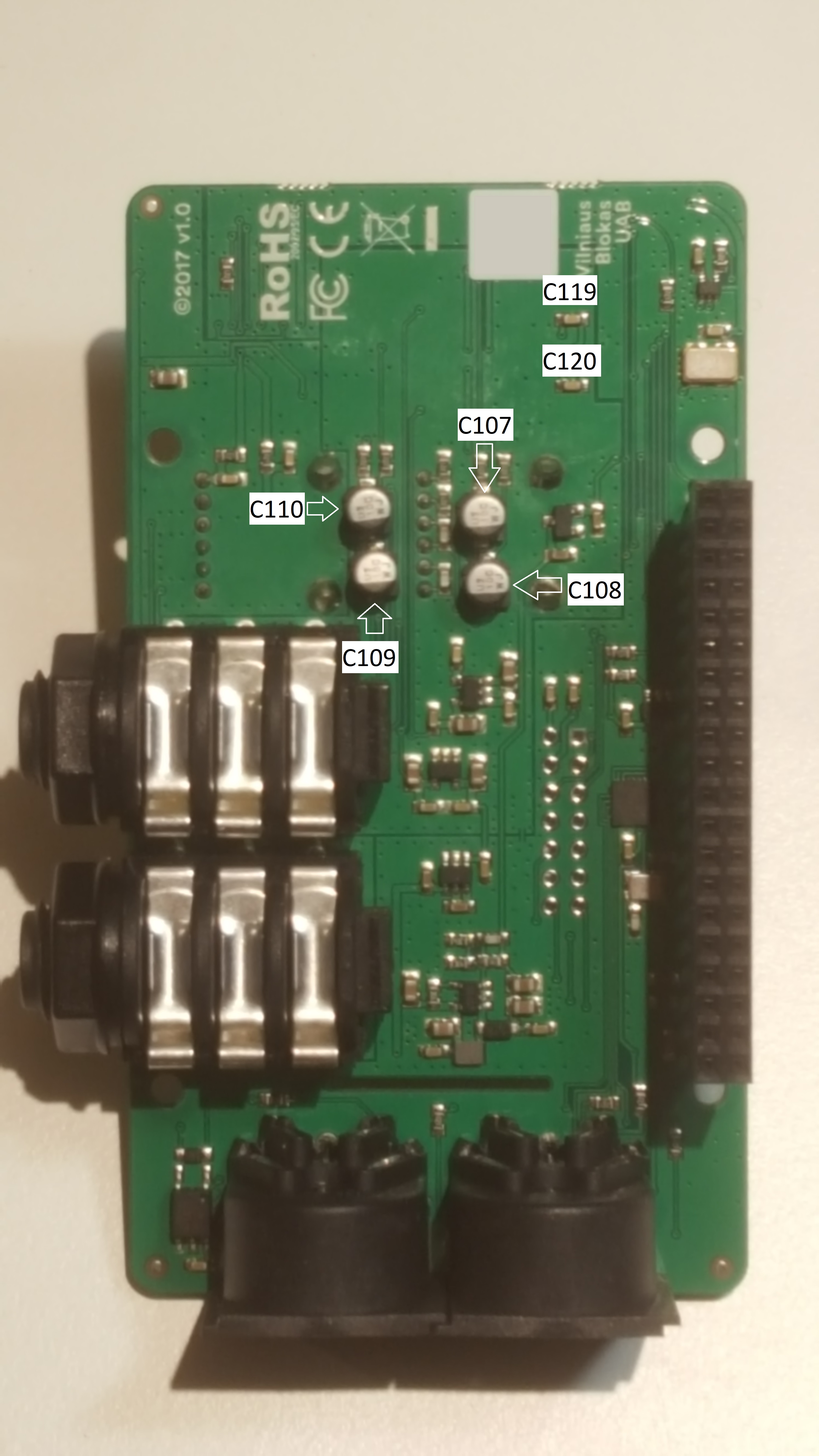
Hey, the Pisound’s anti-alias filter is optimized for audio / musical usage, so that’s why the low pass cutoff is set there. The filters could be changed by hardware modifications (keep in mind that warranty is voided in that case :)), see the below pictures for component locations.

You are right, the input range is 2.5Vpp, we made a mistake in Pisound’s input specs, thank you for pointing this out. When the GAIN potentiometer is at its lowest value, 2X gain gets applied to the input signal, this is useful for low-voltage inputs such as guitars and microphones, and this still covers 0 dBu signal level. The input range can also be modified by replacing some components.

There’s groups of components which must be kept at the same value, they will be tied together with ‘=’ symbol.

High pass filter

A ceramic capacitor valued between 10nF to 1uF should be added in parallel for each electrolytic cap C107=C108=C109=C110 (10uF).

C101=C102 (2.2uF) ceramic capacitors should be replaced with higher value ones, or matching electrolytic capacitors valued between 10uF and 100uF should be added in parallel.

Low pass filter

C119=C120 (10nF) ceramic capacitors should be replaced with lower value ones.

C113=C114=C115=C116 (2.2nF) ceramic capacitors should be replaced with lower value ones.

5Vpp input range

R117=R118=R119=R120 (2.2kΩ) should be replaced with 1.1kΩ valued resistors. Alternatively, 2.2kΩ valued resistors can be added in parallel for each listed resistor.

Top side

Bottom side

1 Like

Hi Giedrius,

Thanks a lot for this very complete answer.

Could you tell me C119=C120 and C113=C114=C115=C116 values to set the low pass filter frequency between 90 and 95 kHz?

I don’t expect strong noises upper 96 kHz so i guess i don’t risk strong aliasing.

Many thanks by advance for your help.

Hey, sorry for the delayed response, here are the details of the mod, including simulated bandwidth graphs:

pisound_emu.zip (377.7 KB)

Conditions of simulation:

  • The impedance of the signal source is 0R (ideal); the resistance of signal source and C102 (2.2uF) (left, C101 for right) is working as high-pass filter;
  • The capacitances of electrolytic caps are ideal; to repeat those results in reality, please add MLCC in parallel;
  • Power supply is considered ideal for Op-amps;

Bandwidth Graphs:

  • Original:
    • Values unchanged;
  • HFexpand:
    • C119,C120,C113-C116 changed to 1nF;
  • LFexpand:
    • C107,C109 changed to 47uF;
  • LFandHFexpand:
    • both mods mentioned above.

Looks like they all should be changed to 1nF ceramic caps. :slight_smile: