I just received and assembled my Midiboy, up till the point where it can be tested over USB. At this stage, when I power it from a USB cable, it won’t show anything on the screen.
With a multimeter I’ve measured between gnd (midi pin as suggested in another post) and pin 6/7 of the Atmega, and I’m only measuring about 1.25V there, while I was expecting 5V. I haven’t soldered in quite a while, so it isn’t pretty. The joints look mostly ok to me, so I’m not sure where to start troubleshooting.
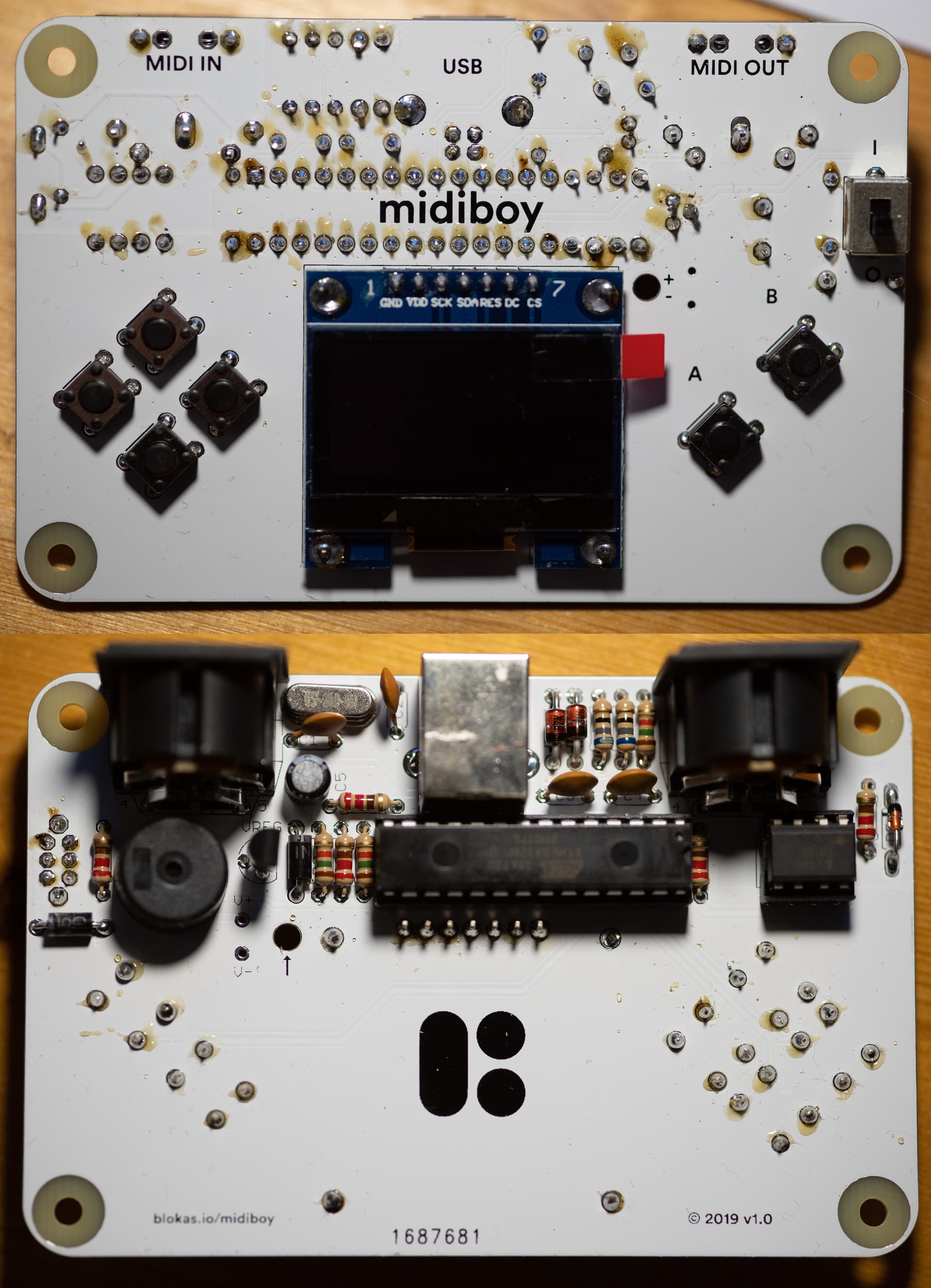
I’ve taken a photo of the front and back of the board, but as a new user I can only attach one of them here. Any guidance would be welcome.
Hi, what voltage do you measure between the GND pin (you can use the MIDI OUT pins at the very top right, which you probable were referring to) and the VDD pin on the screen?
Ok, thank you for the information. The ATmega chip may be the issue - due to our packaging mistake, some Midiboy kits ended up with an unprogrammed micro controller.
The quickest solution would be to program the chip using some external programmer. I could help with that. If you don’t have any, we’ll just send you a programmed chip, just reach out to us by email with your info.
Thanks for the quick response. That’s unfortunate. Luckily, I did find an Arduino Uno development board, which I think I could use to flash a bootloader. I’m in the process of getting some of the software set up.
Is there a ‘known-good’ hex file I can use with avrdude, or should I build from source?
lfuse: CE (recommended to be set as the last thing during programming, see below)
(the lfuse setting sets it up to use an external crystal as the main clock source, in case no clock is available on the XTAL pins (like when wiring it up for programming on an external board), the chip will stop responding, until you connect some 8 MHz - 20 MHz crystal with a ~18pF bypass cap on each of the two XTAL pins.)
Once the Midiboy bootloader is running, select USBasp programmer in the Arduino IDE to upload sketches. Port can be set to anything, it is getting autodetected when using USBasp.
Thanks, I spent a while trying a few options. At first I thought I could just swap the atmega with the one in the arduino Uno, but that didn’t turn out to be the case. Then I investigated the ArduinoISP sketch, but I don’t have the other necessary components at hand (crystal and filter capacitors). I also checked if I could flash it through my Bus Pirate (avrdude claimed to support it), but ran into some firmware compatibility issues.
I don’t think I can easily flash this myself, mostly due to my lack of experience and lack of a supported external programmer.
Ok, thank you for trying, please contact us by email.
This might work, as long as you first flash the hex file, set the efuse, hfuse, and set lfuse as the very final step. The controller won’t respond anymore without an external clock, but if you place it into the Midiboy board, it might just work.
Thanks again for the quick response and for sending a replacement controller. I’ve replaced the controller with the new one and now everything works perfectly fine. I’m playing with the stepollo tracker and it is great fun! Hats off for the prompt response and for helping troubleshoot.