I know, I know…I was supposed to be working on upgrading MODEP to 1.10…but I have a more pressing need. I really wanted to have a small floor based MIDI controller that I could use with MODEP when playing live. I found the one mentioned here at treefallsound.com but I already have my PiSound card and matching case for my setup. I also wanted the option to NOT have to break out the MIDI pedal in situations where I might not need to change my sound. I also wanted the ability to change pedalboards in MODEP in the same device. There are MIDI pedalboards out there but they are all very generic and certainly don’t have the ability to select a pedalboard from MODEP. So…I decided to make one.
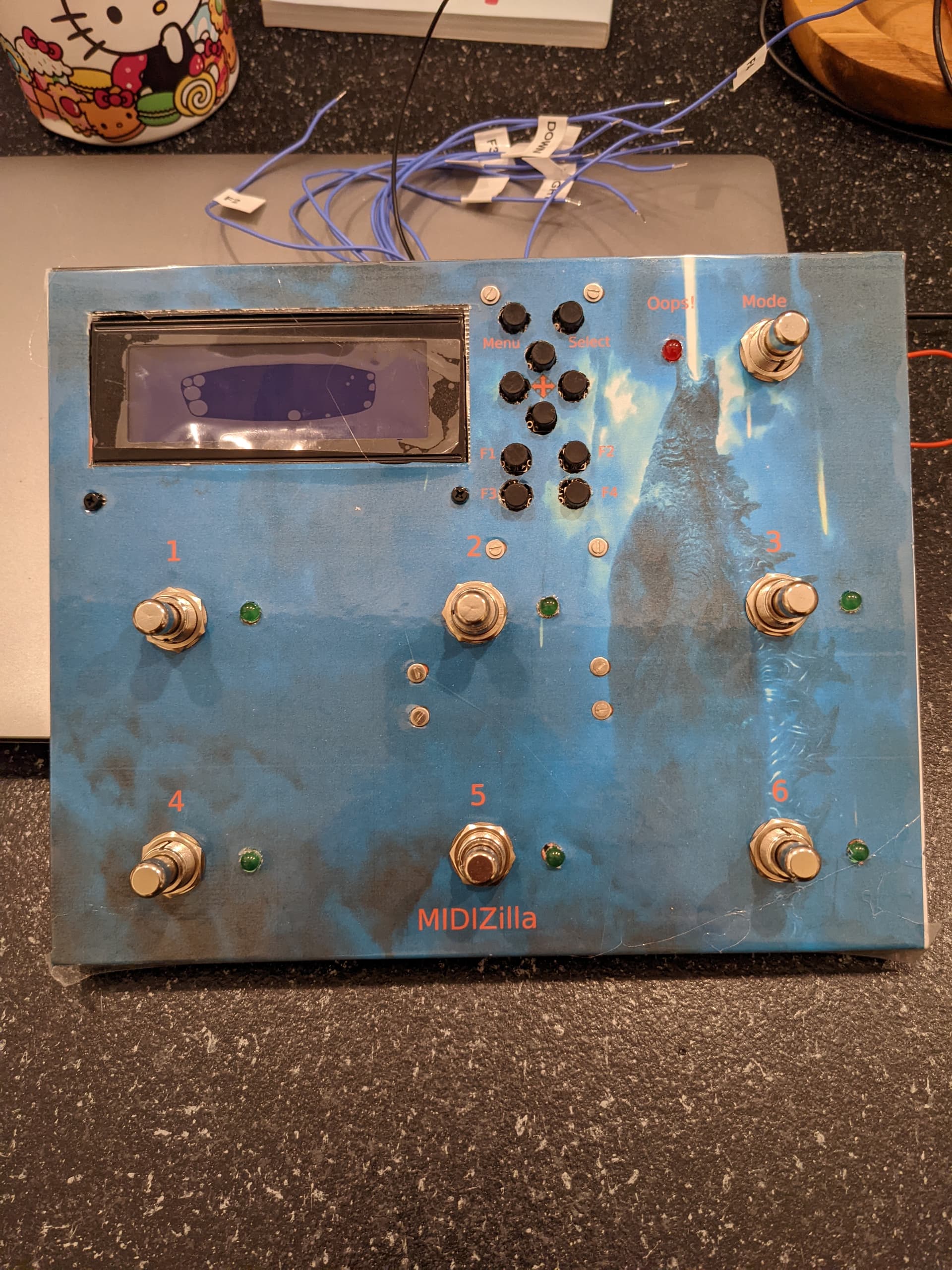
With the recent release of the Raspberry Pi Pico W (“W” means it has wifi) I embarked on creating a MIDI pedalboard that could also connect to MODEP to select a pedalboard. Happy to report that I am getting VERY close. Attached is a picture of what I’ve dubbed “MIDIZilla”.
6 programmable switches that can be mapped to any MIDI CC (0 to 127). To the right of each switch is an LED that will toggle on/off as the switch is pressed.
The LCD in the upper left shows a small description (4 characters) of what each footswitch does and this label can be changed.
The set of buttons to the right allow for changing the pedal’s settings. Through these buttons you can create one or more “Mappings” (MIDI CC and label for the 6 switches), edit the MIDI CC and label for each button, enable/disable a button, create a new mapping, delete a mapping, etc.
4 function buttons. F1 currently allows you to switch between upper, lower, numbers and symbols when editing text on the LCD. F2 is a backspace character when editing text on the LCD. F3 is not currently used. F4 is hooked to the “RUN” pin on the Pico W. Pressing F4 once resets the microcontroller and runs the main code. Pressing F4 slowly twice puts the controller in “safe mode” where it won’t run the main code. Useful when you write code that crashes the microcontroller.
The switch on the upper right is a Mode switch where you can press while playing and select a Mapping. After pressing the Mode switch you can press switch 3 for up and switch 6 for down. Once you have selected a mapping pressing the Mode switch again loads the mapping.
A red LED to the left of the Mode switch turns on if the microcontroller code runs into an error.
There is an expression pedal jack on the right hand side (code not yet implemented because I don’t have an expression pedal)
USB Connection on the back
The board can be powered off the USB port connected to the PI.
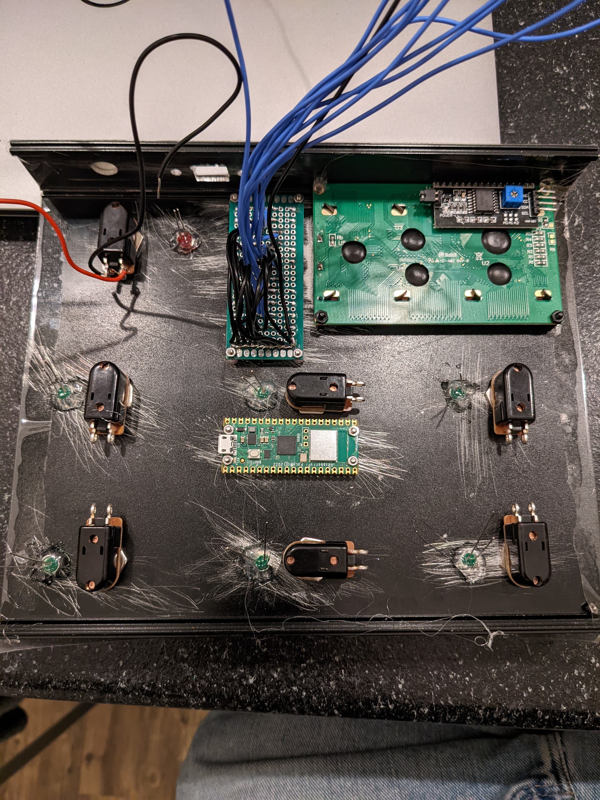
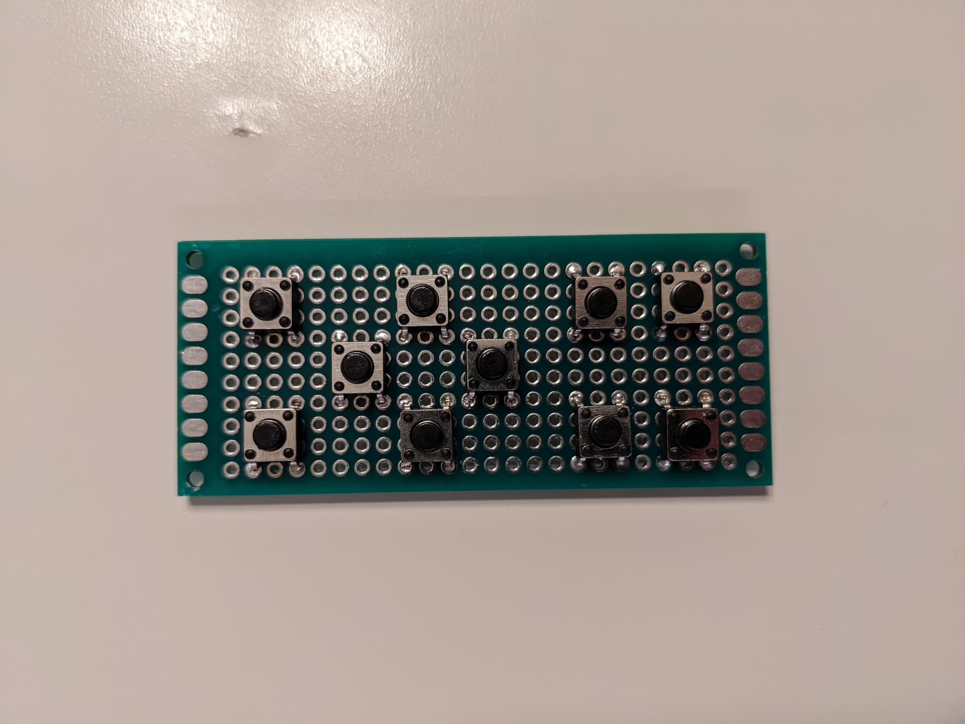
The button panel is a custom panel that I created with simple tactile switches and PCB board.
The code on the microcontroller is custom written by yours truly. I’m using CircutPyton currently and the only drawback is the wifi module on the Pico W is not yet supported in CircuitPython. I could use MicroPython but it lacks USB midi support which is more important to me at the moment. When CircuitPython enables support for the wifi module I will add code to connect to a MODEP instance. Then pressing the MODE switch will allow you to load a pedalboard in MODEP. At that point the code will also look for a mapping that matches the selected pedalboard and load that mapping.
One of my primary goals in this project was to keep the cost to a minimum. That’s why I chose a character LCD instead of a TFT or similar. I did get the 4x20 LCD so I could have more lines/characters to work with.
Everything needed for this board can be purchased on Amazon. If anyone is interested I will also supply the code that will need to be loaded on the microcontroller as well as a Scribus document that you can use to cut out the holes for the enclosure. Let me know and I can post a list of items that I purchased for the project. FYI, Pico W are hard to find right now, hopefully supply will get better soon.
I used an aluminum enclosure and if I did this again I might pick ABS plastic box. Cutting out the LCD/USB holes was a pain as I don’t have great tools at home for cutting rectangles into metal.
I’ll try to post a video of the unit in action once I get all the connections made.
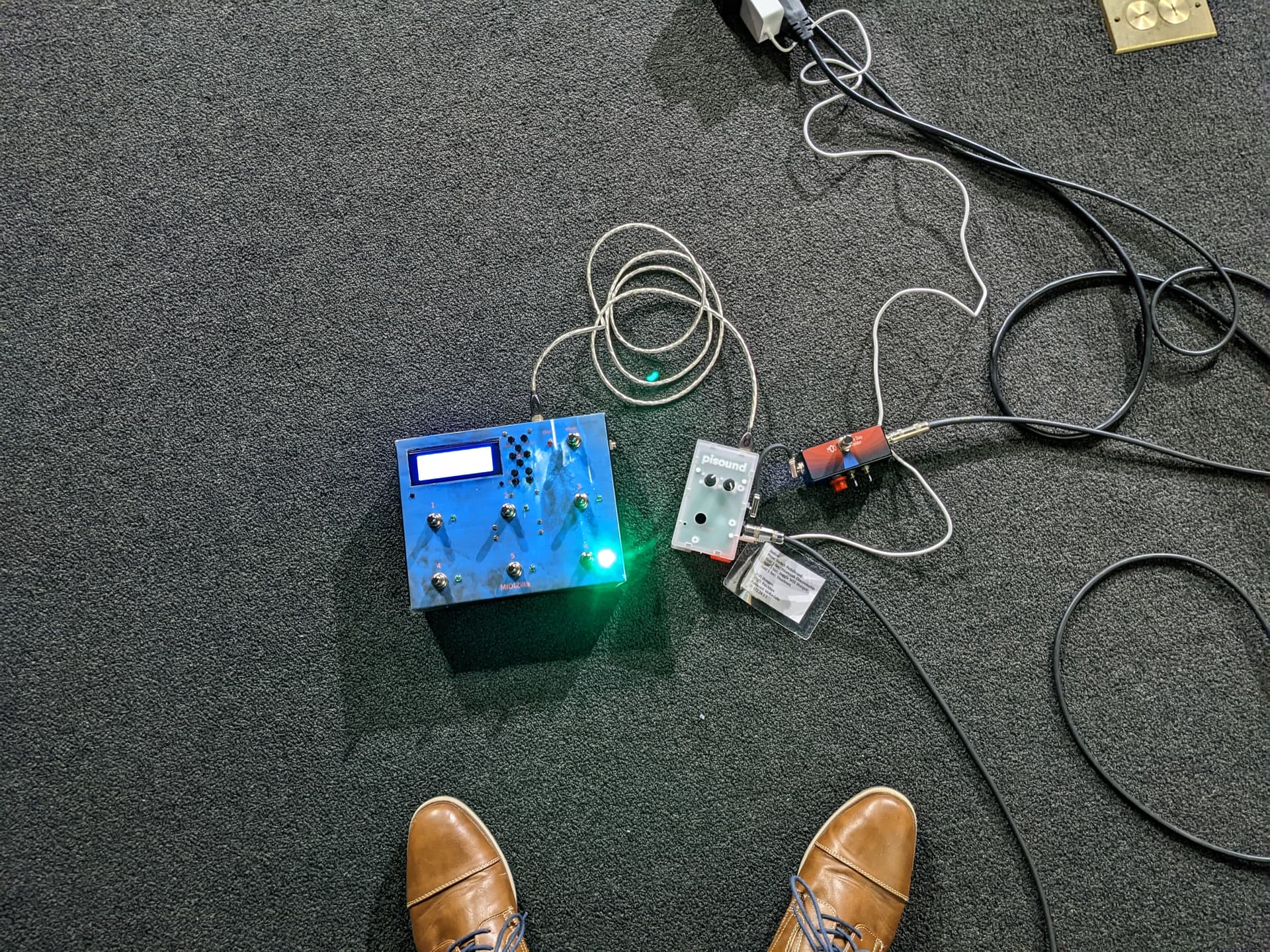
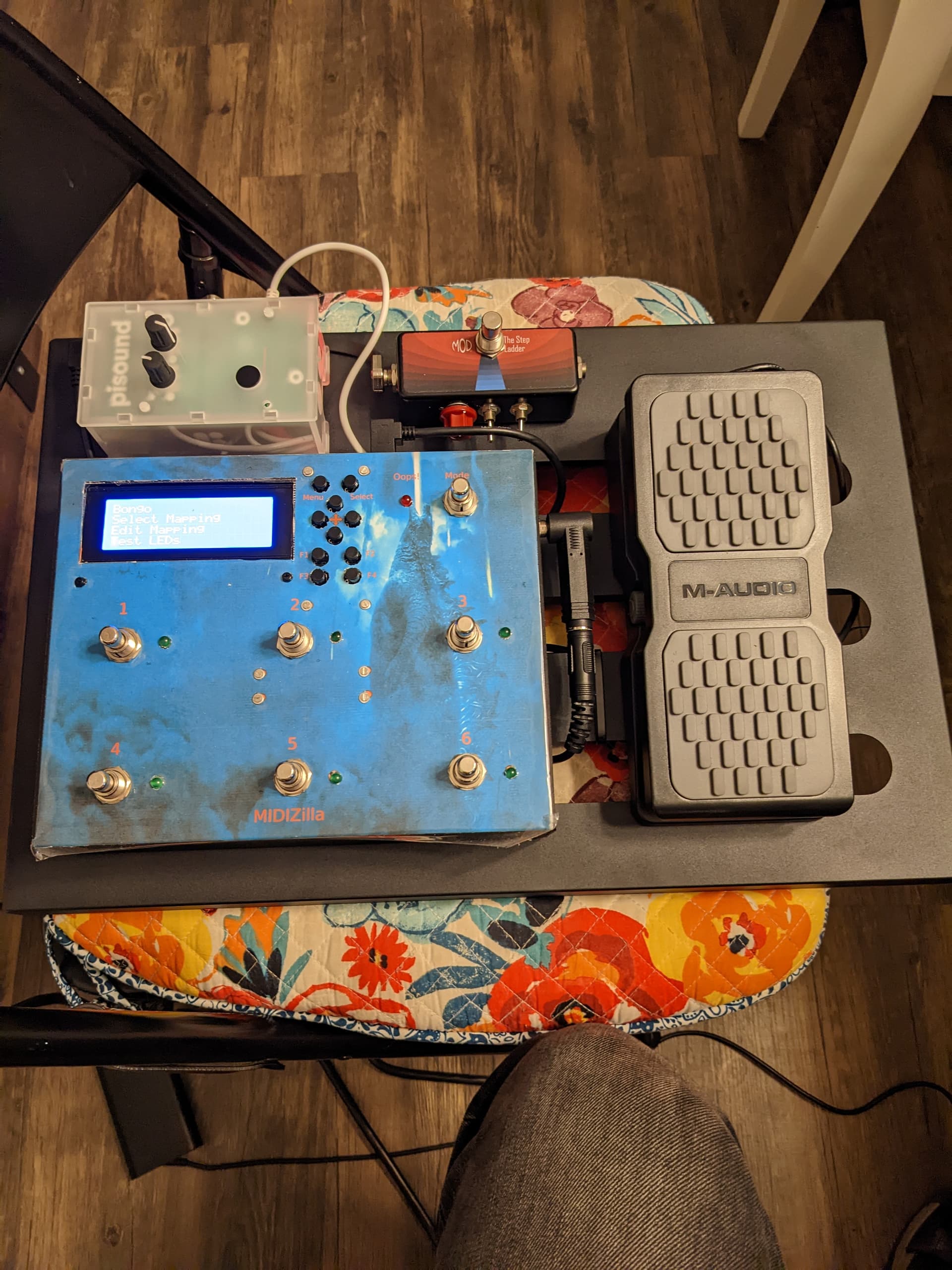
More progress! Got the expression pedal wired up and working. Then I decided to get a pedal board so I don’t have to hook this stuff up every time. Can’t wait to try it out
And just for the record, I would love to see an input pad option and an xlr direct out in a future version of the pisound card. For me I don’t need the midi ports so that would be a perfect spot for xlr out.
Another thought in the input pad. Would it be possible to have the gain pot maybe go from -15db to 25db? Still a 40db range but allow padding input for active instruments?
Okay, if anyone is interested there are 2 github repositories that you’ll need to review:
and
MIDIZilla is the the main guts of the program and lcdzilla is a helper library I wrote for creating structured screens to use with character LCDs. I will also add a list of the components that I purchased for my box.
One note is the MIDIZilla repository has a .sla file that is used with Scribus as a template for where the holes should be cut for the various switches/leds/ports. Your setup may be different but you should be able to slightly modify the file in Scribus for your box if you choose to build one.
As mentioned above, I bought an M2.5 standoff kit but could have used some smaller ones for the PCB button board and the RPi. I wound up just going to the local hardware store and finding some small bolts/nuts/plastic spacers.
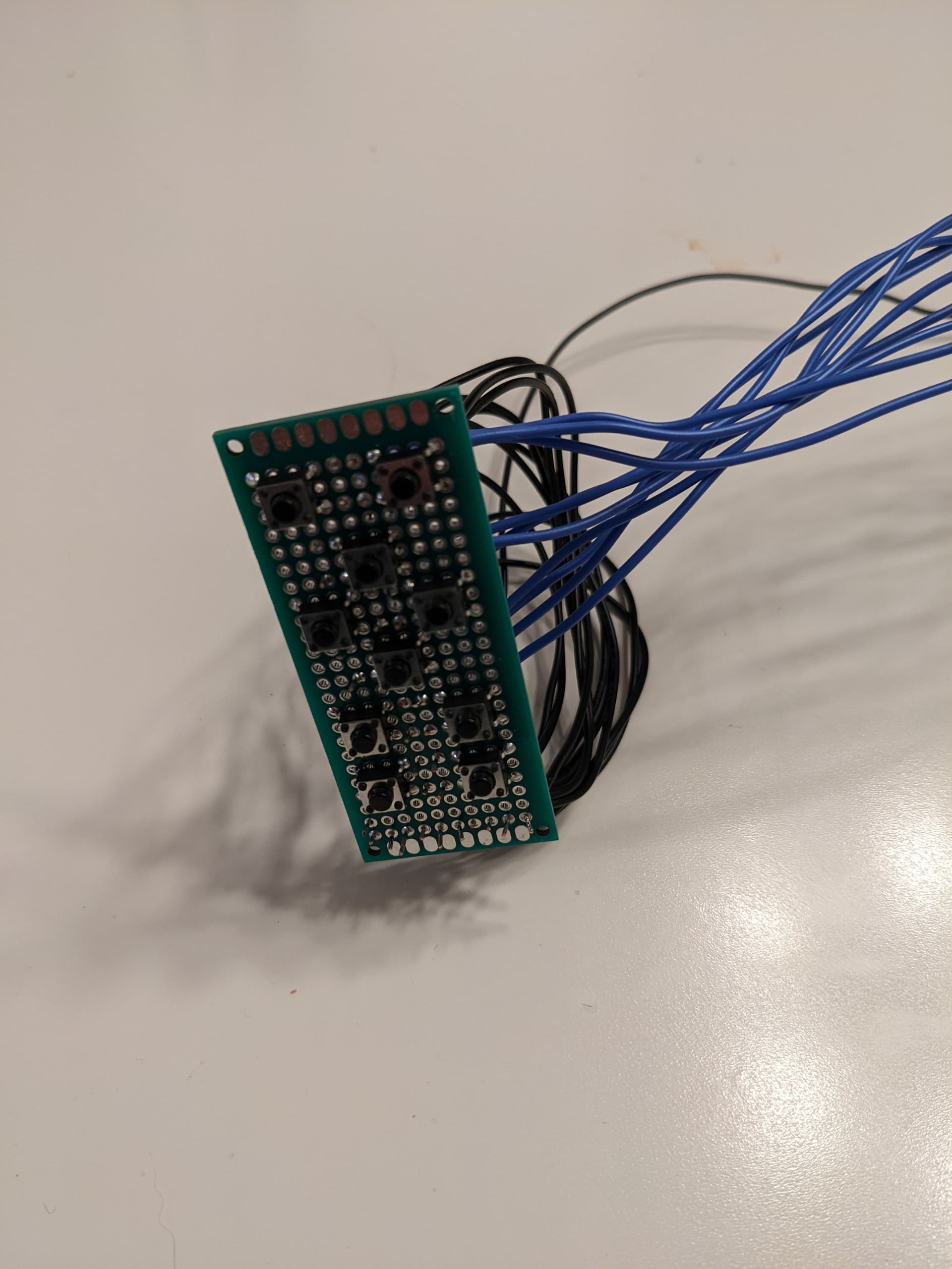
Here’s a few pics of the custom button board and the inside of the box. For the custom button board each blue wire is connected to the “hot” side of the button. The black wires all converge to the bottom of the board where I basically made a ground bus bar that all connect to a single common ground wire that goes to one of the ground pins on the RPi.
Good or bad I wound up just hot gluing the LEDs into place. They seem to hold pretty well and they’ll be easy to replace if one goes out. I did the same common ground technique on the LEDs but just jumped the ground wire from one LED to another and attached the ground wire from the last LED to the RPi.
I have a document somewhere where I mapped out which wire connects to which pin and I will upload that here as well.
Great project! I too have been working on a MIDI controller using the non-W Pico. Honestly the only complaint I have with the board is the dearth of ADCs. Otherwise it’s a really cheap and capable microcontroller for small projects like these!
Did you get the wireless MIDI working yet? I’d love to do that too, if I make a second version of my controller.
@KAOSS I never went back and figured out how to make it wireless. I guess I’m a little old school in this regard because I would rather just have a solid cable connection between my MIDI controller and MODEP. In truth the controller is mounted on a pedalboard right next to the Pi so it never travels far enough to warrant being wireless. And my concern would be that something doesn’t connect and I’m in a place where I don’t have my laptop to triage. Just seems more reliable for a performance controller.
I’m working on the next version of the software that runs on the Pico. When done, it will be able to show the “current” pedalboard/snapshot and the buttons along with their label/function will come from the current pedalboard loaded in MODEP. For example, I would map the 6 buttons to MIDI channel 70 - 75 on the Pico. The software on the Pico would then match up those channels to current pedalboard. If the current pedalboard mapped a control to channel 70 then that button is enabled and the label comes from MODEP directly. If there is not use of channel 70 on the current pedalboard then that button will be “Off”.
Long pressing the “Mode” button on the controller will show the list of pedalboards available in MODEP. Pressing footswitch 5 or 6 will move the cursor up/down the list of pedalboard. Pressing the “Mode” button again will cause MODEP to load that pedalboard. Short pressing the “Mode” button on the controller will cycle through the snapshots available for the current pedalboard and update the name on the LCD. For example I have a pedalboard named “NAM” since it uses the NAP plugin. I have 4 snapshots with 4 different bass amps loaded into NAM. Short pressing the MODE button will display: “NAM - GK700RBii” then another press would display “NAM - SVT” and so on.
The other feature I’m going to implement is through the menu/option buttons on the controller. There will be an option to display information about MODEP/Pi:
MODEP Version
PI’s IP Address
PI’s temperature
etc
And another option to list/execute scripts on the Pi:
Turn on wifi hotspot
Turn on bluetooth
Reboot the Pi
I’m currently able to connect the Pico to the Pi and have the Pi detect when the device is plugged/unplugged and how to make it reliable enough to just unplug at any point then plug back in and reconnect. Getting that conversation worked out is a bit harder than I thought.
Another thought: It’s awesome to see the various projects that people create for interacting with MODEP. My goal is to create a controller that is simple to use in a performance setting. I like the MODEP interface for configuring a pedalboard but I would hesitate to use it in a performance setting. I like to get my pedalboard fully configured before I play then just a few switches to turn on/off a small set of options.
I do get wanting it to be wired, as it is more reliable every single time. I was just curious as to how you were going to make them talk wirelessly.
I’m eager to know how you will be making the Pico talk to the Pi for stuff like which of the CCs (I’m assuming that’s what you meant) are mapped in a pedalboard. Is it through browser-based requests, or is there some MIDI commands for that?
How much is the time delay between switching NAM profiles for you? For me, I found it to not really be useful for playing live. At least that was my experience on the Pi 4 with standard-mdl profiles.
Yes it does seem to be detected every single time it’s plugged in once the amidithru and the mod-midi-merger services are going.
I have also been working on a MIDI controller project of mine using the Pico as the brain. I’m going to make a post about it soon. Would love to hear any suggestions you might have regarding it!
@KAOSS I’m going to answer a couple of your questions together. First off, the Pico running CircuitPython actually exposes 3 interfaces:
The REPL port which is used by editors to communicate with the board and echo output for testing
A MIDI device
A serial data interface
Initially I was under the impression that you could only have the MIDI port OR serial data interface on at any given time but that was not the case. You can actually have all 3 active at the same time. So my current approach is to use the serial data interface to handle the communication between the Pico and the Pi for getting current pedal board information, the list of available pedalboards, loading different pedalboards, changing snapshots, etc (MODEP stuff). There will be a Python program running on the Pi that will listen for the serial connection and once the connection is established MODEP data will be exchanged. To get the MODEP data I’m using the Rest Web APIs provided by MODEP.
The MIDI device exposed by the Pico will remain unchanged since I will still use that to send MIDI commands to the Pi.
Basically I’m using CircuitPython’s USB serial library for making the connection to the Pi. On the Pi I’m using the standard Python serial library to connect to the Pico. I would assume that if you wanted to communicate to the Pi via wireless it would have to be over wifi or bluetooth but exactly how I never got that far.
As far as switching NAM profiles, I just use Snapshots to load various profiles into NAM. It’s instantaneous.
Feel free to clone by github repo for MIDIZilla to see how I implemented sending CCs to MODEP.
Oh that’s interesting! Looking forward to see your implementation. Where can I find the details on the Rest Web APIs?
To be sure I tried it again. I have a guitar pedalboard that has separate post FX chains depending on the type of sound – heavy rhythm, lead, and cleans.
On the Pi 4 it does take a bit of time to switch NAM profiles using snapshots. You can definitely hear the switch when the output of NAM goes through the current snapshot’s FX chain while it is still switching from the previous snapshot’s assigned profile. I’d say it takes like 200 - 300 ms.
On the Pi 5, it definitely takes a lot less time and seems like it’s done in like 50-ish ms. However it’s still not what I’d call “seamless”.
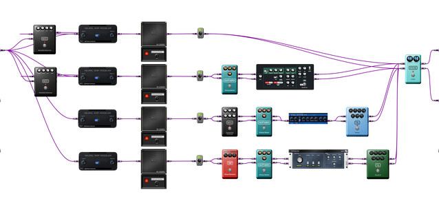
To get around this, my main pedalboard has four full chains running in parallel. I can load 3 standard NAM profiles and one Nano profile on the Pi 4 at 48kHz, 128 samples and 2 periods. I have to keep the buffered switch on otherwise it’s too much for the Pi 4. The switching is pretty much instantaneous, but it does take a toll on the CPU usage. I’m pretty much at the limit of the Pi 4.
Maybe this switching delay is because of the number of FX in my pedalboard? Could you share a screenshot of your pedalboard? I’d like to see how complex it is.
I’ll send you a screenshot later of my pedalboard but watching the video you shared on our private message I see that you’re basically running all 4 NAM plugins at the same time and I assume you’re muting those with the volume control?
I think a better way to do this would be to look at the 4 way selector switch plugin and only route signal to one chain at a time:
Yes indeed. Basically keeping the chain I need on and muting everything else. The way I run it allows me to switch between the sounds instantaneously with no “bleed” (described below), as well as preserve the delay and reverb trails when switching to a different snapshot.
For anyone reading, this is how it’s set up:
Initially that’s how I had planned on doing it. Definitely would’ve brought down the CPU usage quite a bit. However as I’d mentioned previously, it does lead to “bleed”, i.e. say I’m switching from my heavy sound, which has no post FX, to my clean sound, which has a delay and a reverb. When I use snapshot to switch between my NAM profiles and handle the mute states of the TinyGains, the required mute state of the TinyGains is achieved immediately. However there’s a delay between the sound to that of the new profile in NAM. This leads to the heavy rhythm sound going through the clean post FX for a bit, before it switches to the clean sound.
These audio examples demonstrate it better hopefully:
First is the file with the four parallel NAM instances.
Then we have the file with a single NAM instance switching between profiles with snapshots:
Notice how much smoother the transitions are with the parallel pedalboard as opposed to the one with the single instance. Also the single instance pedalboard seems to cause a lot of XRUNS, whereas the other one doesn’t.
@KAOSS I will post my collection later this evening.
I did listen to your recordings and not exactly sure what you’re trying to achieve. So when you switch from clean to overdrive are you wanting it to be an instant change or are you wanting some overlap between the two sounds?