I want to make a hat circuit board for the pisound, and I wonder if the circuit design of the pisound is available so that I don’t mess up the positions of the pins and mounting holes.
@alexandros you can find Pisound’s mechanical drawings here: Pisound board dimensions - pcb board art 
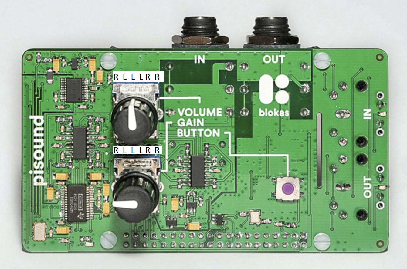
Thanks! Though this is (as you mention) the mechanical drawings. I’m a bit confused with the volume stereo pot. Since I’ll design a hat for the pisound, I want to remove the pots and place them on the hat. Measuring continuity with my multimeter, the first four pins of the volume pot (from left to right) are all shorted, as well as all three pins of the output audio jack. Can you please describe the signals on each pin of the volume pot?
Hi, please see the datasheets of the stereo potentiometer parts:
- Input Gain: https://www.alps.com/prod/info/E/HTML/Potentiometer/RotaryPotentiometers/RK12L12/RK12L1230C1M.html
- Output Volume: https://www.alps.com/prod/info/E/HTML/Potentiometer/RotaryPotentiometers/RK12L12/RK12L12C0A0E.html
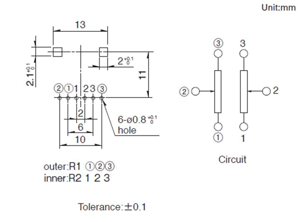
The left / right channel the pin is affecting is marked with ‘L’ and ‘R’ respectively.
Thank you very much! I was looking at those potentiometers today trying to figure out the connections. What about the way they are connected to the audio jacks and to the ADC and DAC chips on the board?
I would guess that pin 1 of the volume pot is connected to GND, pin 2 to one of the two channels of the output jack, and pin 3 to the signal coming from the DAC. Is this right?
For the gain pot I would guess that pin 1 is connected to GND, pin 2 to the ADC, and pin 3 to one of the two channels input jack.
Is that correct or is the configuration different?
This is true.
It’s a bit more involved - the gain pot controls the amplification, rather than the attenuation, of the input signal, each potentiometer pin is on its own net and shouldn’t be connected with any other nets. In case you plan to use a different potentiometer, you may swap pins 1 and 3 to reverse the min/max positions of the potentiometer.
Sort of understood. What I need to know about the gain pot, is which pins connect to the T and R of the input TRS jack. Is it pins 2?
Thanks for the help!
The gain potentiometer and the input TRS connector do not share any connection. The gain pot controls the gain of the amplifier to which the audio signal is connected to.
That makes total sense. Had to think twice I guess. Thanks for the help!
Would it be possible to give us a vector file or even 3D file of the pisound so I could more easily create an enclosure I like?
@microfx sorry for the delay, here is the Pisound 3D model (STL).
pisound-model-STL.zip (658.6 KB)
And here is the reference model of Pisound & Raspberry Pi combo.
pisound-raspberry-model-STL.zip (2.5 MB)
Let me know if you need them in any different format. 
If possible I would love to have these files i STEP or f3d format. 
pisound-model.zip (1021.6 KB)
pisound-rpi-model.zip (7.4 MB)
Here you go! 
I don’t understand
the OP asks for circuits, you give him 3D files ???
It’s a response to the enclosure 3D files request just above Pranciskus post.
ok
is the schematic available ?
No, it’s not publicly available.